OBJECTIVE: Learn the sources of bio-potentials in the human body and understand the techniques used for measurement of these electrical potentials.
BACKGROUND ON BIOPOTENTIALS:
All cells of an animal maintain an electrical potential gradient across their cell membrane. This is accomplished by using various ionic pumps on the cell surface. These potentials are usually below 100 mV, and inside of the cell is negative with respect to its surroundings. For example, cardiac cells maintain a potential difference of approximately 90 mV when they are polarized. Although most cells maintain this gradient with very little change, some cells do depolarize, temporarily loosing the potential difference between the intra-cellular and extra-cellular environment. This is usually accomplished by opening gates on the cell membrane to allow the passage of ions such as sodium, potassium and calcium. When that happens, the potential difference between the two sides of the cell membrane diminishes or sometimes even reverses for a period of time. This mechanism used by nerve cells to carry impulses, and by muscle cells for triggering mechanical contractions. When multiple cells depolarize either simultaneously or sequentially, they generate an electrical waveform which can be detected by external electrical circuits. For example, the depolarization of cardiac cells produces the ECG (Electro-Cardio-Gram), which will be studied during this lab experiment.
BACKGROUND ON ECG
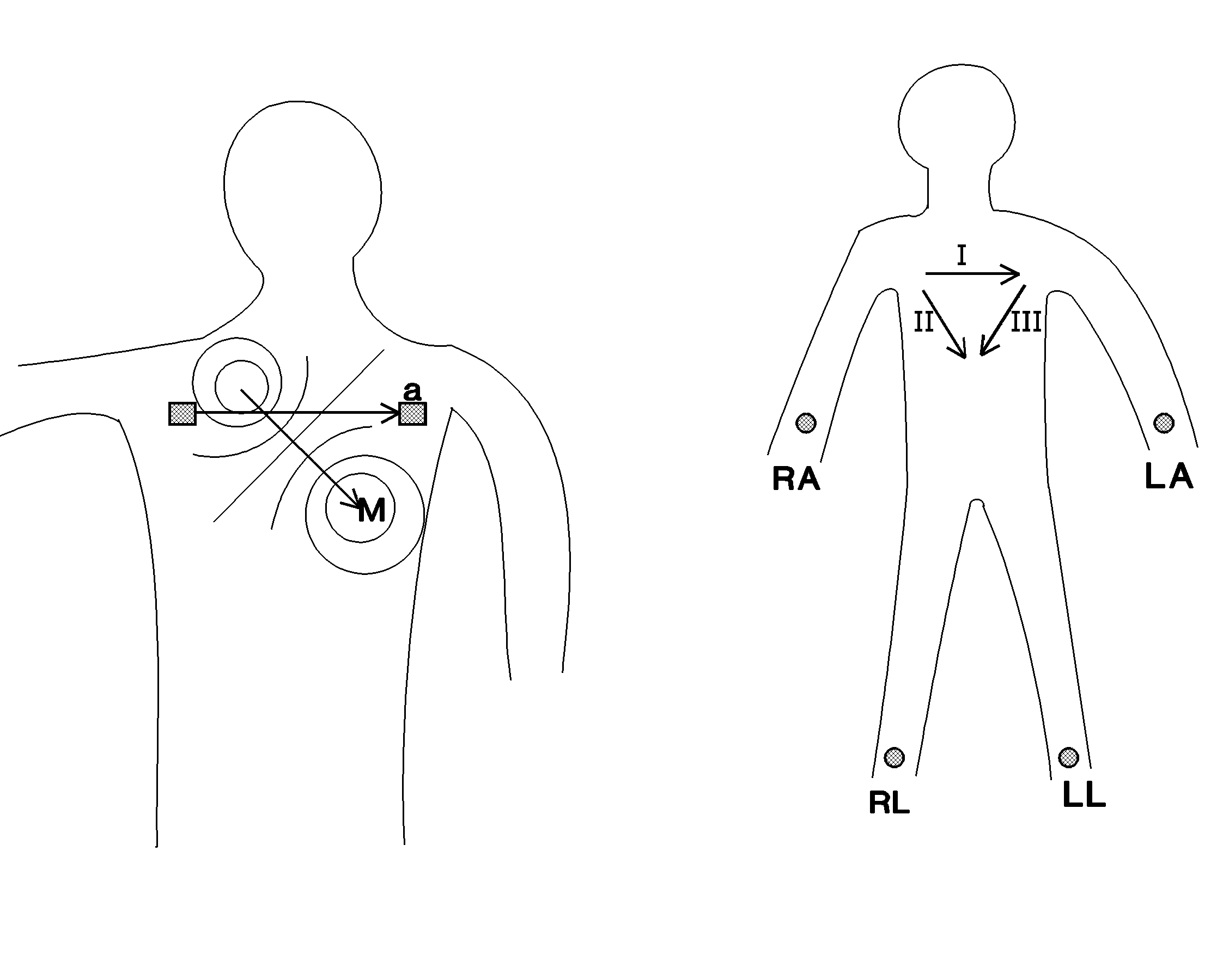
Electrical activity of the heart can be approximated by a dipole (a vector drawn between two opposite electrical charges) with time varying amplitude and orientation. For this simplified model, we will represent the cardiac dipole vector with M. If two electrical leads are connected to human body at two different locations, we can draw another vector in space, a, from one of the electrodes to the other. Electrical voltage observed between these two electrodes is given by the dot product of these two vectors.
![]() [Equation 3.1]
[Equation 3.1]
Figure 3.1 below shows the orientation of M and a vectors in relation to patient.

Figure 3.1. ECG vectors in relation to the patient.
There are many different configurations to place the ECG electrodes on a patient. Three common ones are listed below in Table 3.1.
|
Lead 1 |
+ LA - RA |
|
Lead 2 |
+ LL - RA |
|
Lead 3 |
+ LL - LA |
Table 3.1. ECG Lead configurations.
Short hand notation used in Table 3.1 is explained in Table 3.2 below:
|
LA |
Left Arm |
|
LL |
Left Leg |
|
RA |
Right Arm |
|
RL |
Right Leg |
Table 3.2. Short hand notations used in ECG descriptions.
One way to memorize the ECG configurations in Table 3.1 is to note that the very last letter is always an "A", and the number of times letter "L" is used on the second column is equal to the assigned Lead number as shown in the first column. For example, Lead 2 configuration has two Ls.
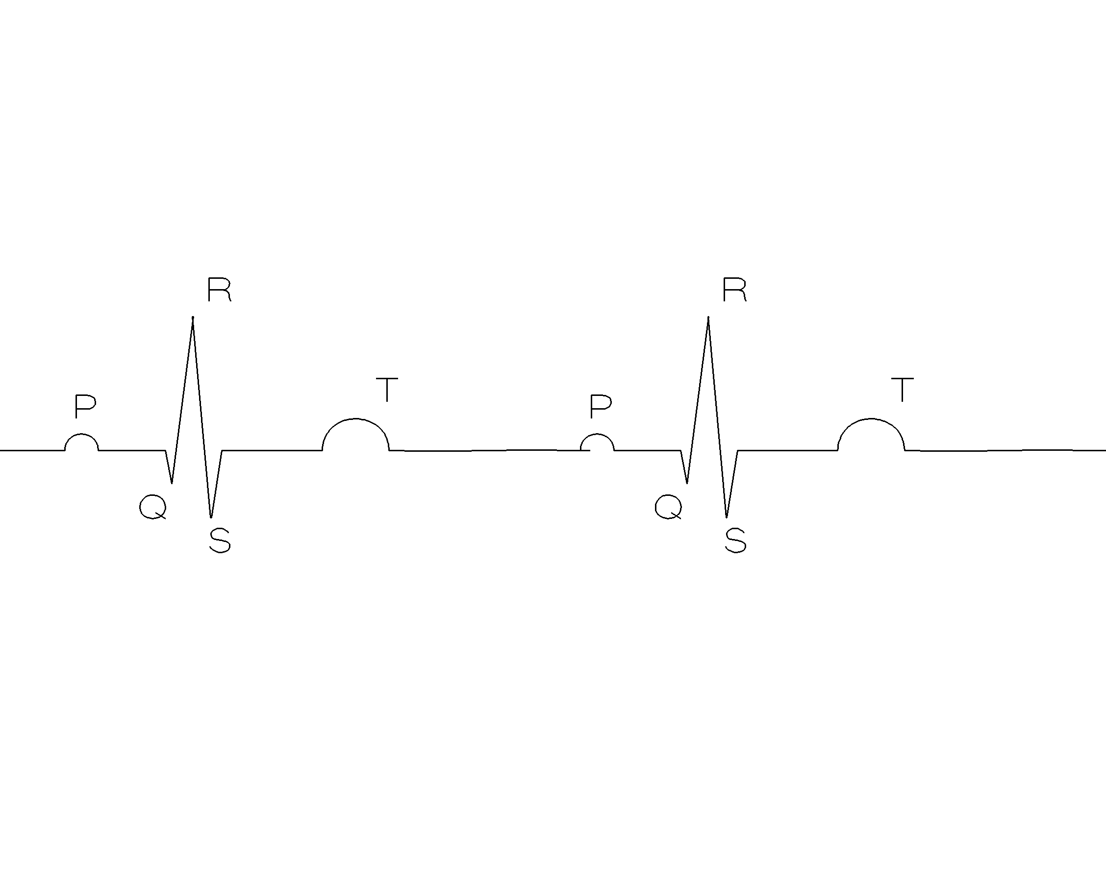
Typical ECG waveform is shown in Figure 3.2 below. P wave is due to the depolarization of the atria, QRS is due to depolarization of the ventricles and the T-wave is due to re-polarization of the ventricles.

Figure 3.2. Typical ECG waveform.
BACKGROUND ON BIOPOTENTIAL AMPLIFIERS:
Bio-potential signals are very weak signals. Even the strongest ECG signal has a magnitude of less than 10 mV. Furthermore, ECG signals have very low drive, i.e. source has a very high output impedance. Therefore, an ECG amplifier is usually required to have the following properties:
Input leakage current is defined as the current an amplifier sends to the unit (human body in our case) connected to its input terminals.
Common Mode Rejection Ratio (CMMR) is defined as the ratio of the magnitude of the differential gain to the magnitude of the common mode gain, as given below:
![]() [Equation 3.2]
[Equation 3.2]
where AD is the differential gain of the amplifier and is given by
![]() [Equation 3.3], and
[Equation 3.3], and
AC is the common gain of the amplifier and is given by
![]() [Equation 3.4]
[Equation 3.4]
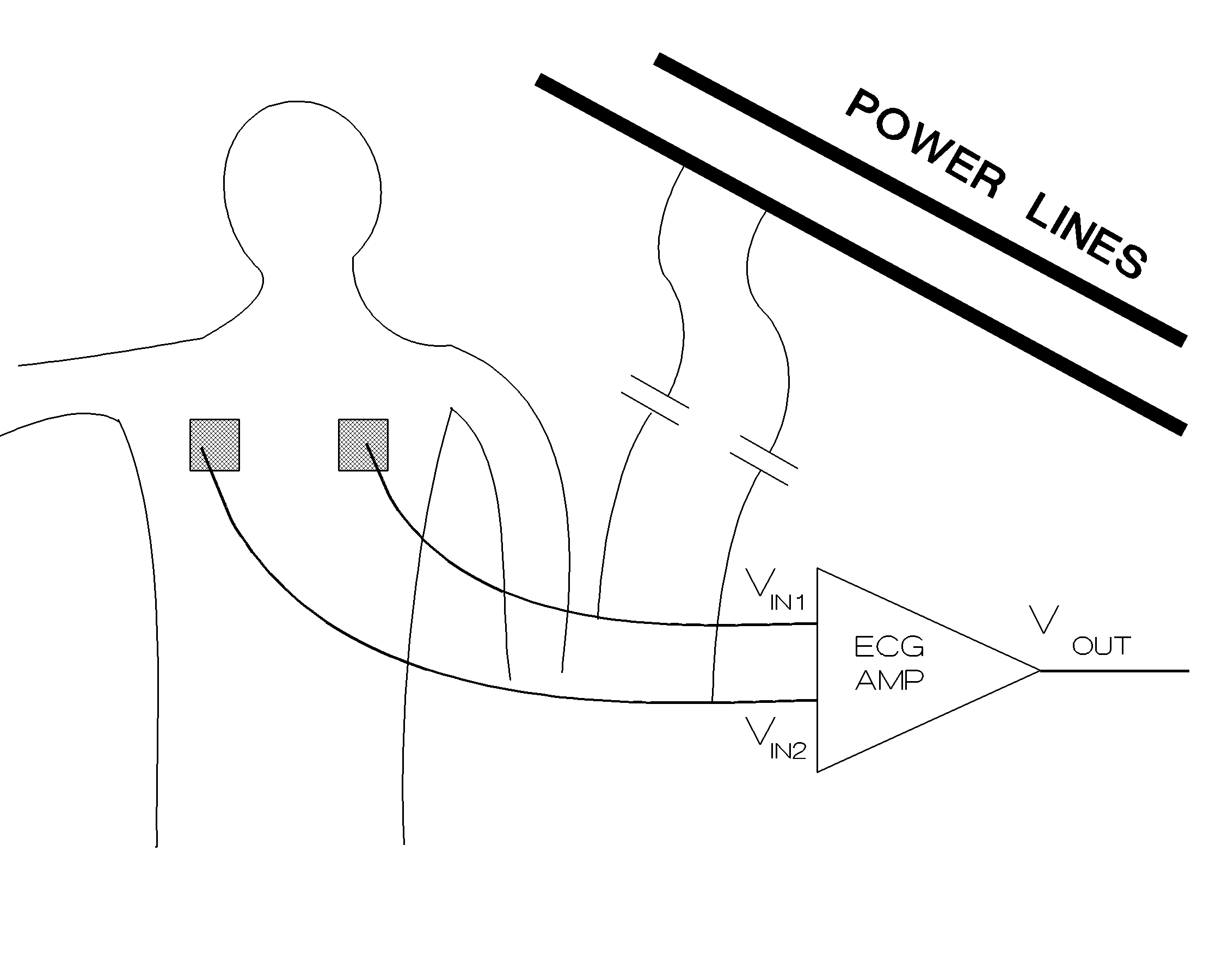
A high CMMR is essential since the capacitive coupling from the external electrical sources such as power lines would create a strong common mode signal in comparison to the differential ECG signal. A high CMMR would mean that the AD is much larger than AC, and the differential amplification of ECG signal in the order of 1 milli-Volt would be possible in the presence of common 50/60 Hz signal coupled from the power mains, which would be in the order of tens of Volts. Figure 3.3 below shows the typical situation in electrical bio-potential amplification.

Figure 3.3. Electrical coupling from the 50/60 Hz power mains to the ECG amplifier.
EXPERIMENT:
REPORT:
|
P-P interval (milli-seconds) |
|
|
P-QRS interval (milli-seconds) |
|
|
Deduced AV delay (milli-seconds) |
|
|
QRS-T interval (milli-seconds) |
|
|
QRS-QRS interval (milli-seconds) |
|
|
Heart Rate (beats/minute) |
|
|
Length of cardiac cycle (milli-seconds) |
|
|
Estimated duration of systole (milli-seconds) |
|
|
Estimated duration of diastole(milli-seconds) |
|