BACKGROUND ON FLOW MEASUREMENT SYSTEM:
Among all the quantities measured in the body, blood flow is one of the most important ones. Blood flow in various parts of the body is indicative of the changes in circulation at that region. For example, if the flow to the brain in reduced, nerve cells begin to dye within minutes, as in the case of stroke. Another example is the aortic flow. Its reduction would indicate a major disruption in the cardiovascular health. Because of that, aortic flow is very closely monitored by cardiologists in patients with heart failure.
Chamber Plethysmography
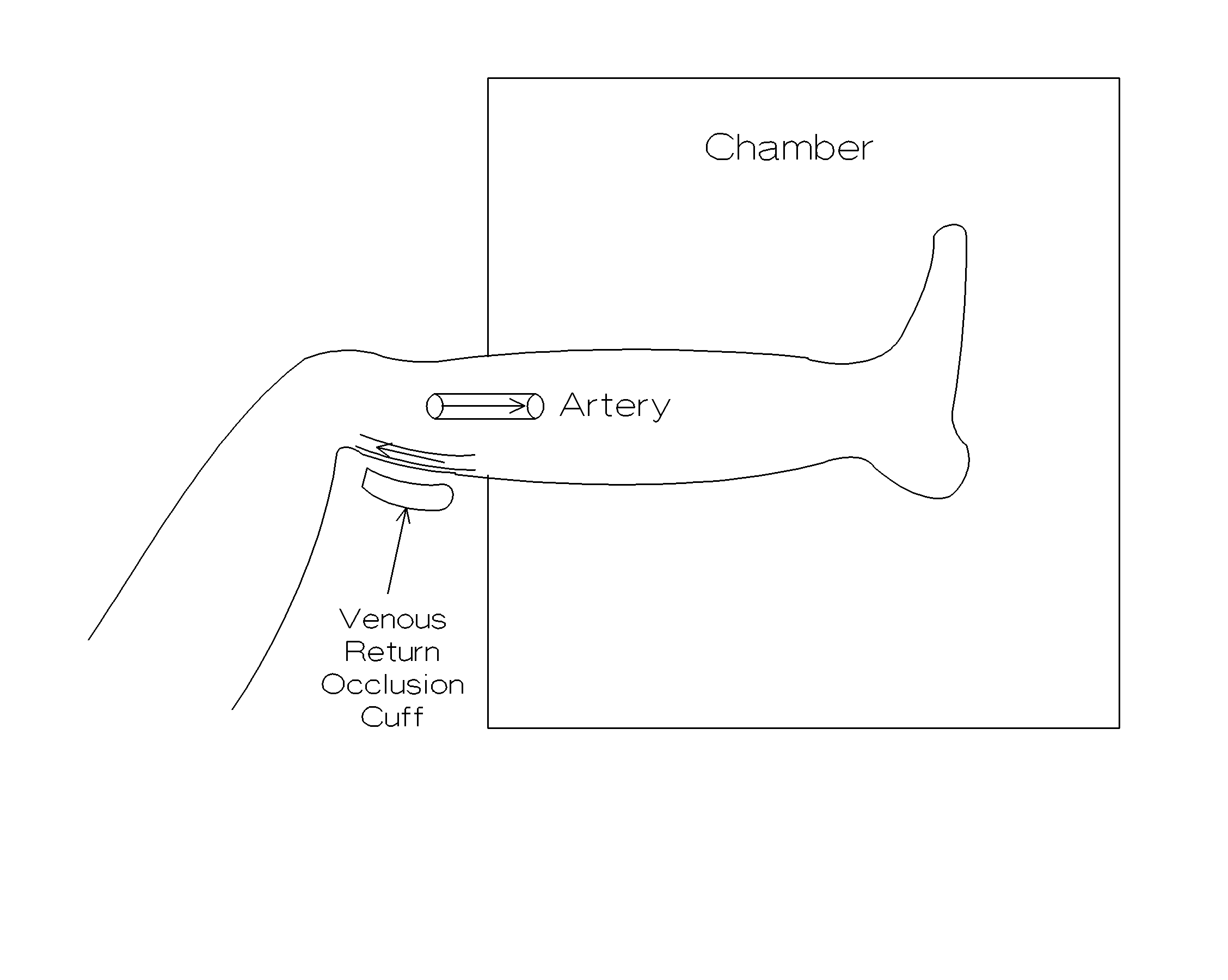
There are many different blood flow measurement systems. One method of flow measurement is to monitor the changes in the volume of an extremity by a technique known as chamber plethysmography. This technique requires that the venous flow from the extremity is occluded by the application of a pressure to the vein. This is possible since human anatomy places the veins close to the surface of the body. Once the venous flow is occluded, arterial inflow will change the volume of the extremity. If the extremity is enclosed in a sealed chamber, then the changes in the pressure in the chamber would be related to the flow as explained below:
In the chamber, temperature is constant. Therefore,
P V = n R T = k = constant [ Eq. 1 ]
or
![]() [ Eq. 2 ]
[ Eq. 2 ]
![]() [ Eq. 3 ]
[ Eq. 3 ]
![]() [ Eq. 4]
[ Eq. 4]
or the flow is given by
![]() [ Eq. 5 ]
[ Eq. 5 ]
Note that this is a non-invasive measurement technique, and can be applied to extremities, not to internal organs like the brain.

Figure 1. Chamber Plethysmography technique applied to a leg to measure the blood flow below the knee.
Thermodilution Method for Flow Measurements
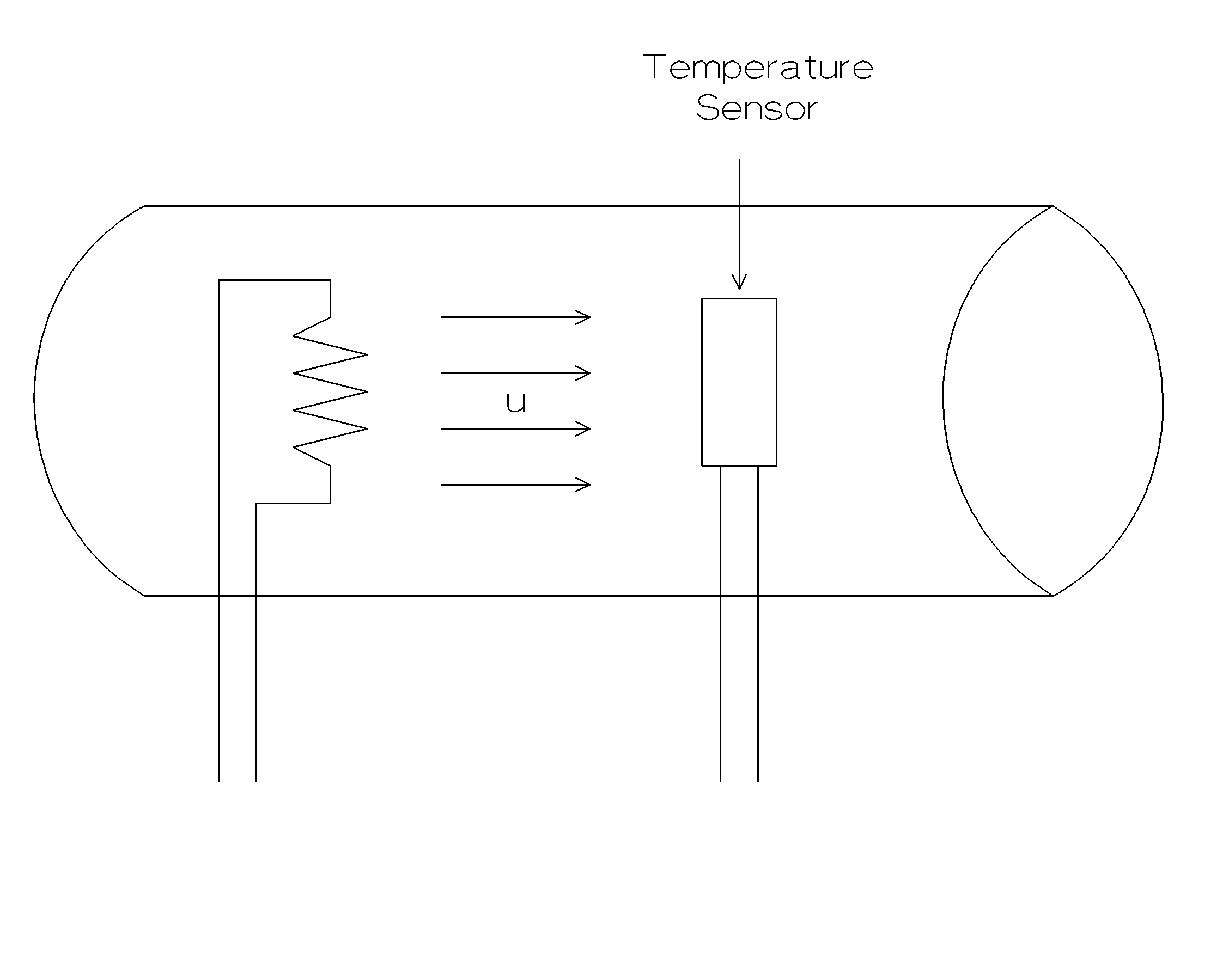
Thermodilution method allows an accurate measurement of average flow in a vessel. Technique is simple. A heater element and a temperature sensor are placed in blood vessel, usually using a catheter. Heater element is upstream, and the temperature sensor is downstream. Operator first allows the temperature sensor to stabilize and obtains a baseline measurement. Afterwards, the heater is turned, which produces a known amount of heat per unit time. Changes in the measured temperature is inversely related to the blood flow. When the flow velocity is high, large amounts of blood passes over the heater, and change in temperature is minimal. On the other hand, when there is a only low blood flow, temperature change would be high since very little amount of blood will receive all the thermal energy released by the heater. Following equations describe the operation of this sensor.
Assume that the heater element is a resistor having a value R. If the voltage applied to the resistor is V, then the power dissipated on the resistor is given by,
![]() [ Eq. 6 ]
[ Eq. 6 ]
If the cross sectional area of the blood vessel is A, and the blood velocity is u, then the volume of blood flowing over the sensor per unit time can be calculated as
![]() [ Eq. 7 ]
[ Eq. 7 ]
We can assume the density of blood is r =1 gr/cm3, and its heat capacity, heatC = 1 cal/gr = 4.19 Joules/gram. Then,
 [ Eq. 8 ]
Solving for blood flow F =Au,
 [Eq. 9 ]

Figure 2. Thermodilution sensor for blood flow measurement in a blood vessel.
Electromagnetic Flowmeters
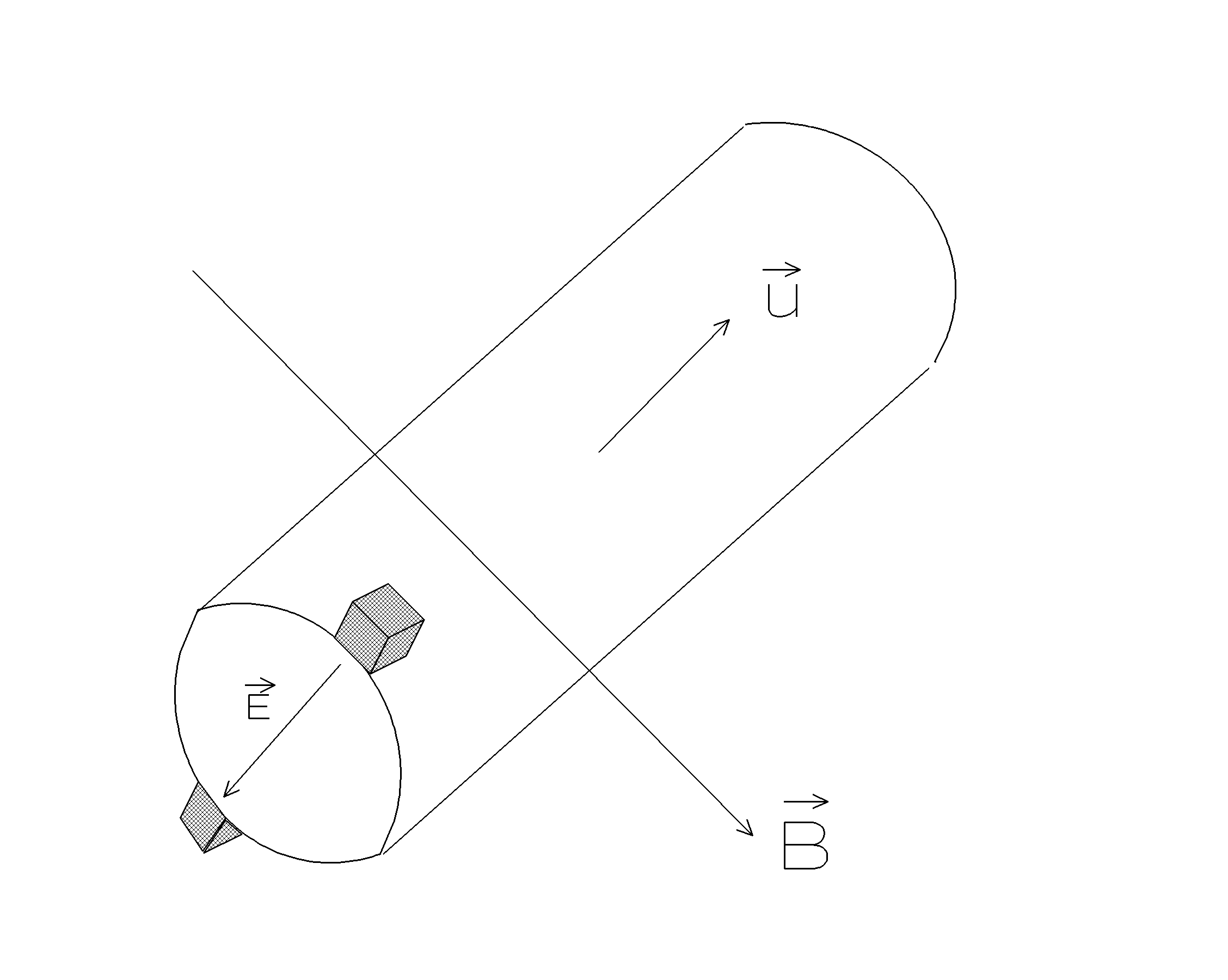
Unlike the thermodilution sensors, electromagnetic flowmeters measure the instantaneous flow of blood. Sensor operation is based on the principle that charged particles moving in magnetic fields experience a force, which is proportional to the velocity u, magnetic field B and charge of the particle, q. Force on the particle is given as
![]() [ Eq. 10 ]
[ Eq. 10 ]
solving for the electric field E,
![]() [ Eq. 11 ]
[ Eq. 11 ]
If all vectors are perpendicular, then
E = uB [ Eq. 12 ]
Voltage between the electrodes can be calculated as the integral of the E field along the distance between the electrodes, d,
![]() [ Eq. 13 ]
[ Eq. 13 ]
In order to avoid the fluctuations of the sensor signal caused by the tissue-electrode interface, alternating magnetic fields are used,
![]() [ Eq. 14 ]
[ Eq. 14 ]
then,
![]() [ Eq. 15 ]
[ Eq. 15 ]
would be the equation for signal observed at the electrodes of the sensor. In order to find the blood flow u, one must measure the amplitude of the sinusoidal function and divide that by B0d.

Figure 3. Electromagnetic flowmeter where all three vectors are orthogonal to each other.
Ultrasonic Flowmeters
Sound is a pressure waveform. It can travel in all media, including the tissue and blood. One can calculate the power in a sound waveform
![]() [ Eq. 16 ]
[ Eq. 16 ]
where I is the power in the sound, p is the peak pressure exerted by the sound waveform, u is the velocity of the particles vibrating due to the travelling sound wave. This sound power decreases as one moves away from the transducer and is given by,
![]() [ Eq. 17 ]
[ Eq. 17 ]
where I0 is the power at the source, a is the attenuation constant, and x is the distance from the source of the sound.
Most ultrasonic devices transmit and receive using the same transducer. If the speed of sound is c, frequency is f, and the wavelength is l , then
c = f l , [ Eq. 18 ]
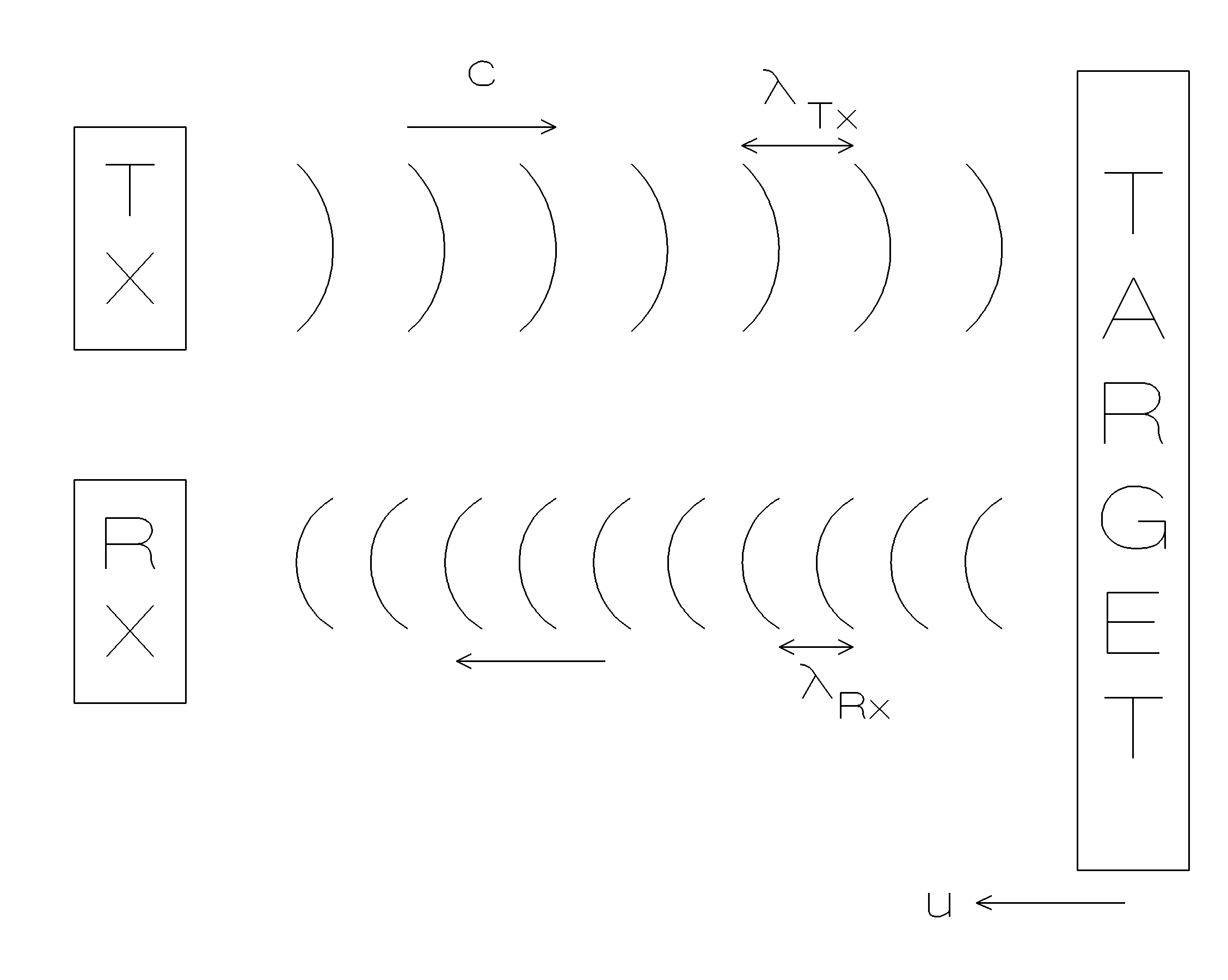
If the target object (usually blood in the ultrasonic flow measurement systems) is moving toward the transducer, time between the two crests of the sound wave would be reduced. Assume that the target is moving with a speed of u,
Tc + Tu = l Tx [ Eq. 19 ]
l
Tx is the wavelength of the incident waveform and T=1/fRx![]() [ Eq. 20 ]
[ Eq. 20 ]
or
![]() [ Eq. 21 ], valid only when u << c.
[ Eq. 21 ], valid only when u << c.

Figure 4. Doppler ultrasound for blood velocity measurements.
EXPERIMENT:
In this experiment we will use a very basic ultrasonic Doppler monitor. This device has two crystals, which allow operations at 5 MHz and 7 MHz. Device also provides audio feedback that can be used during transducer placement.
REPORT: