![]()
BE 306 Bio-Instrumentation (Lecture)
Sample Problem Set 1


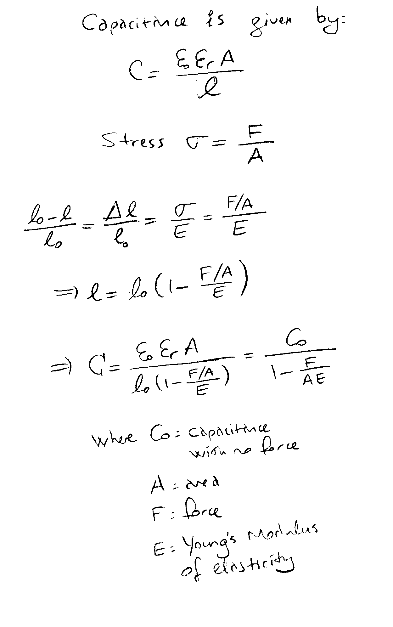
Find the relationship between the applied force and measured capacitance.
![]()
![]() 3. If Rbody = 500W
, and impedance plethysmography uses 1 mA excitation current, how much power is dissipated on the tissue?
3. If Rbody = 500W
, and impedance plethysmography uses 1 mA excitation current, how much power is dissipated on the tissue?
ANSWER: Power = Voltage x Current = V I = (I R) I = I2 R
= (1x10⁻³)2 500 = 5x10-4 = 500 m W
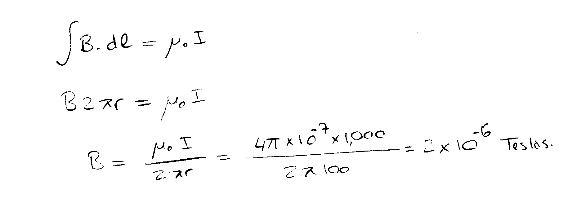
4. A farmer in his house is about 100 meters from overhead power lines which carry 1,000 amps. What is the magnetic field strength in his household?
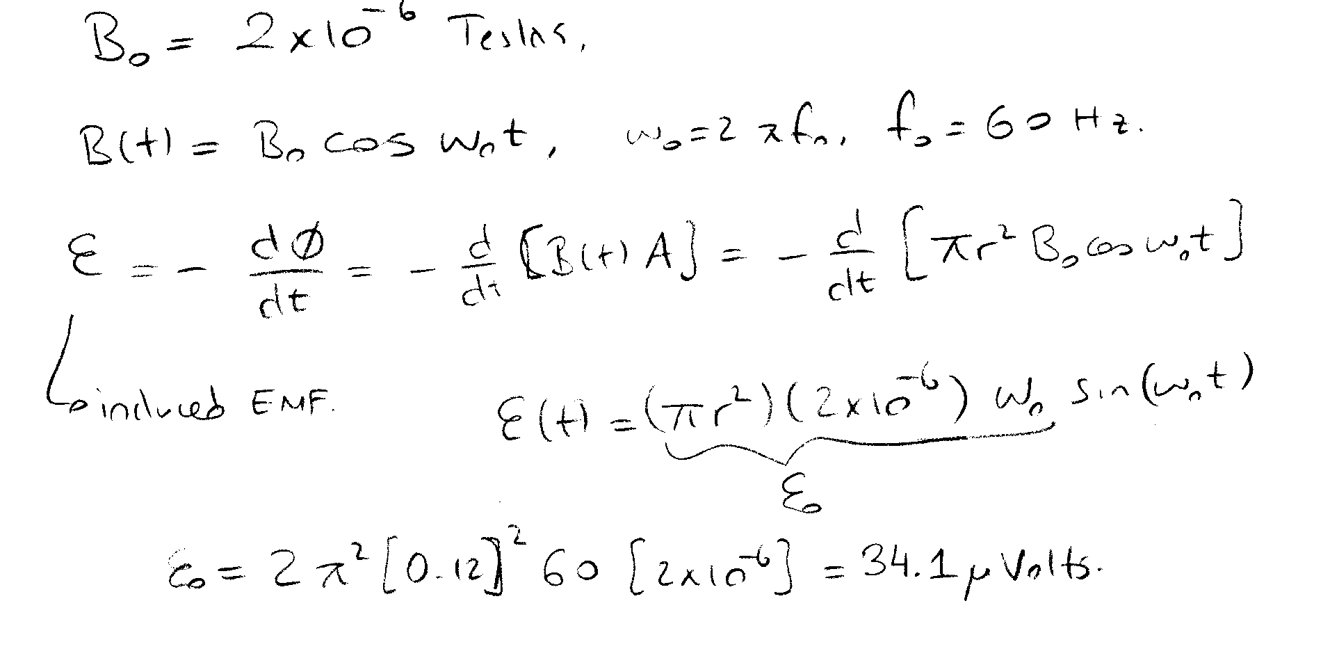
5. Continuing the example above, if fo = 60 Hz, and the radius of the farmerís head is 12 cm, what is the induced voltage within the circumference of his head?
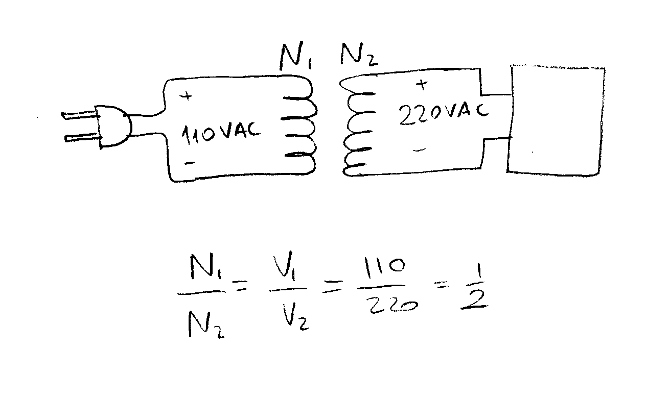
6. A patient isolation transformer is required to be used in the USA, where the power supply is 110 V, for a piece of German-made Siemens equipment which is designed to be powered by a 220 Volt supply. What is the ratio of primary to secondary windings of the power transformer?
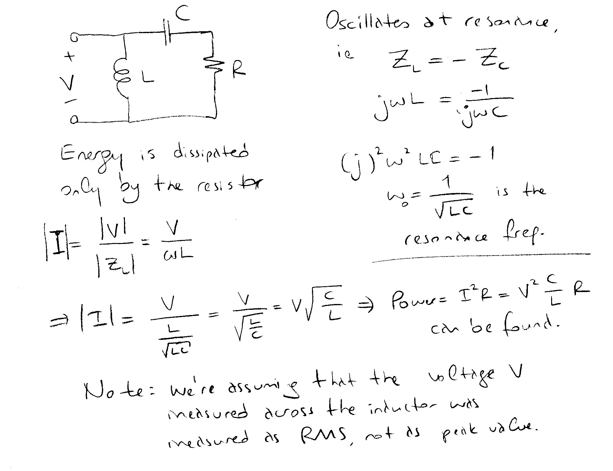
7. For inductance plethysmography, we have an oscillator with a series RLC circuit. It oscillates at V volts. What is the energy dissipated in the tank circuit?
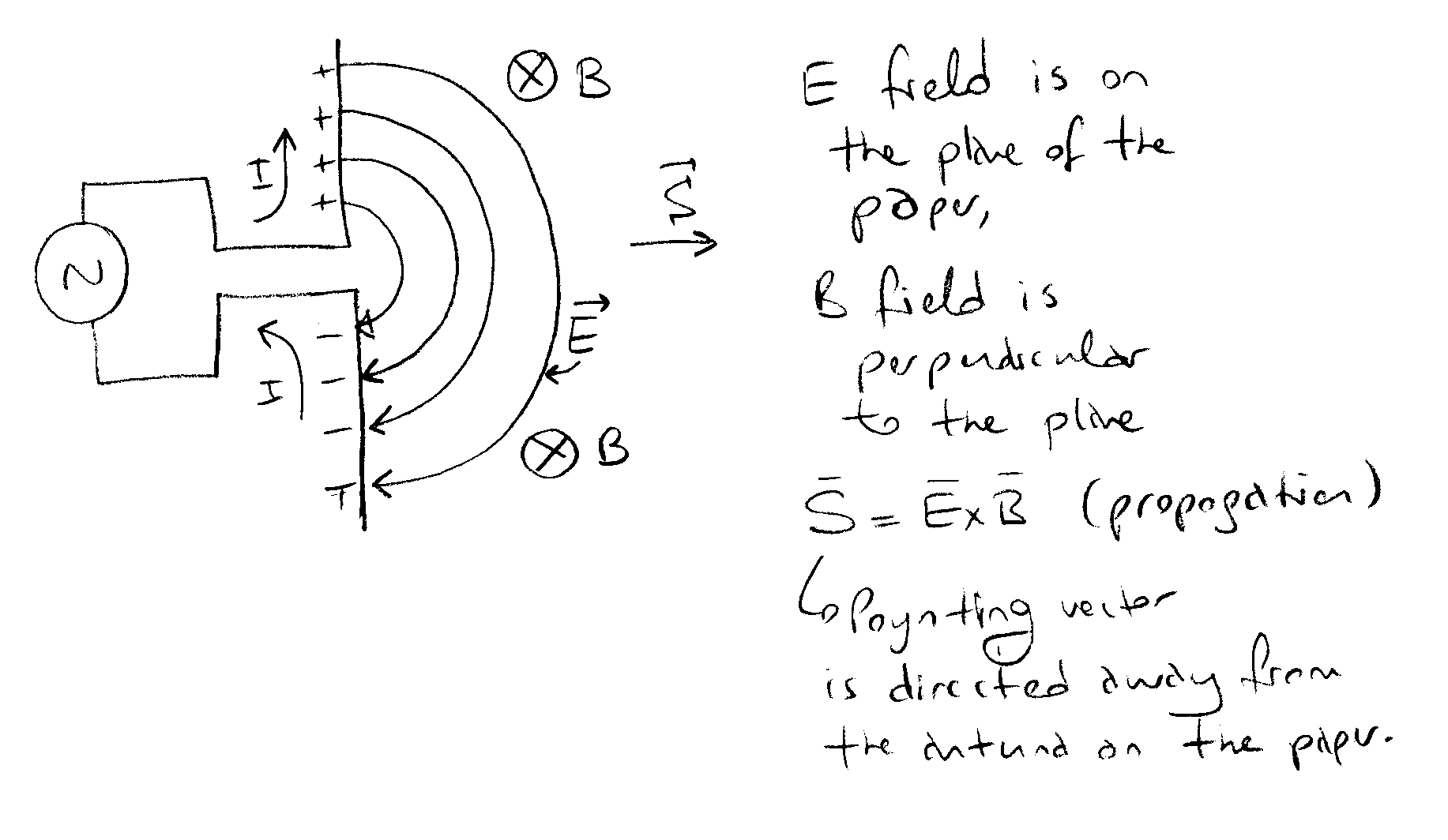
8. A dipole transmission antenna is lying on the plane of this paper. What are the orientations of the Electrical and Magnetic fields?
9. Explain how Scanning Tunneling Microscopy works.
ANSWER: See page 17 of class notes.
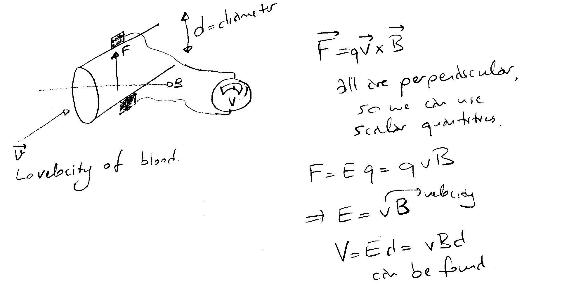
10. Derive the equations describing the operation of the electromagnetic flow sensor.
(a) V(t) = aT(t) + b (NON-LINEAR)
(b) V(t) = aT(t Ė z), where z is a constant (LINEAR)
(c) ![]() (LINEAR)
(LINEAR)
(d) V(t) = eaT(t) (NON-LINEAR)
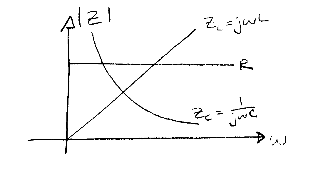
12. Plot the electrical impedance of a resistor, inductor and capacitor as a function of frequency.
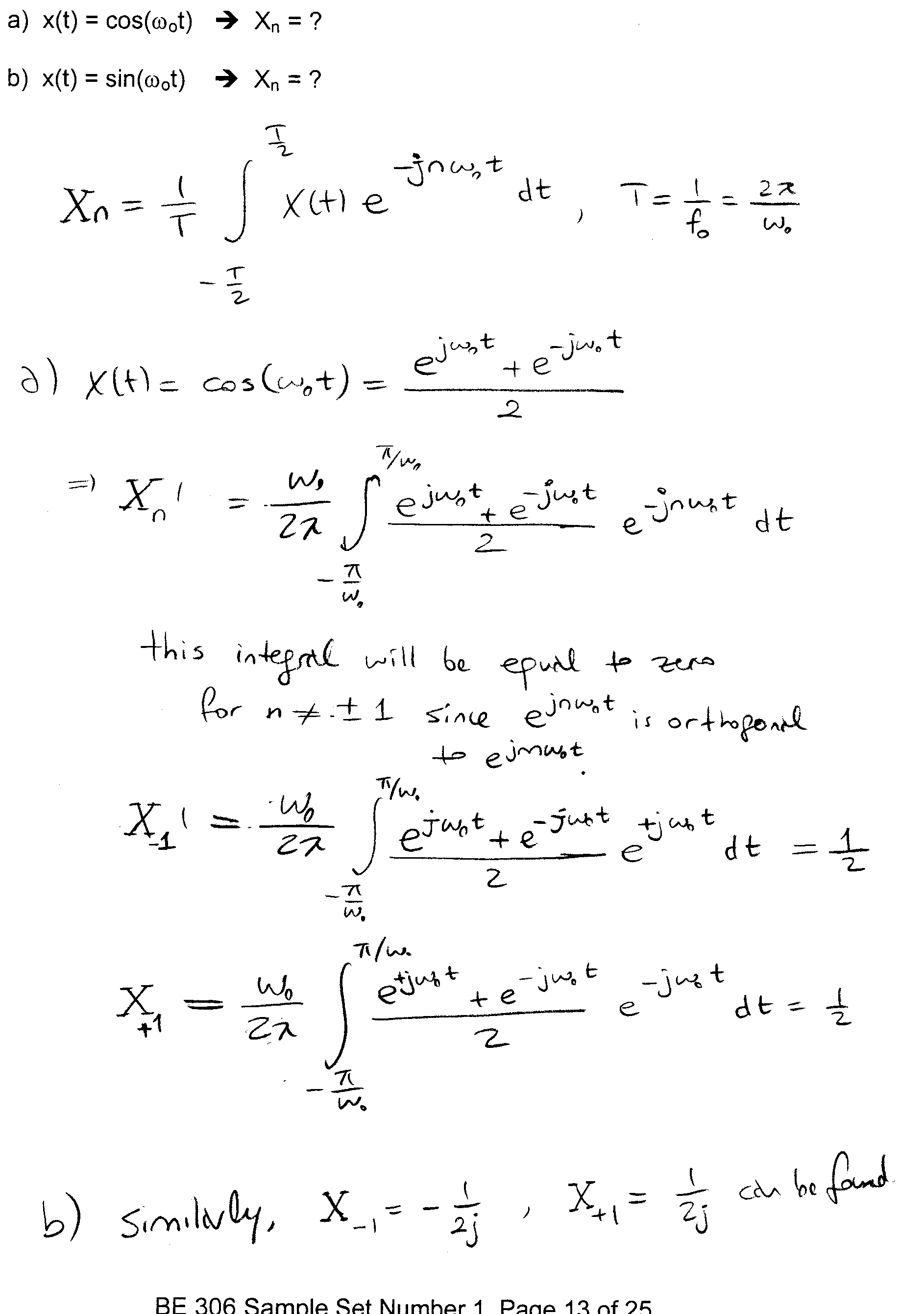
a) x(t) = cos(w ot) è Xn = ?
b) x(t) = sin(w ot) è Xn = ?
14. Derive the input/output equation for the following system:
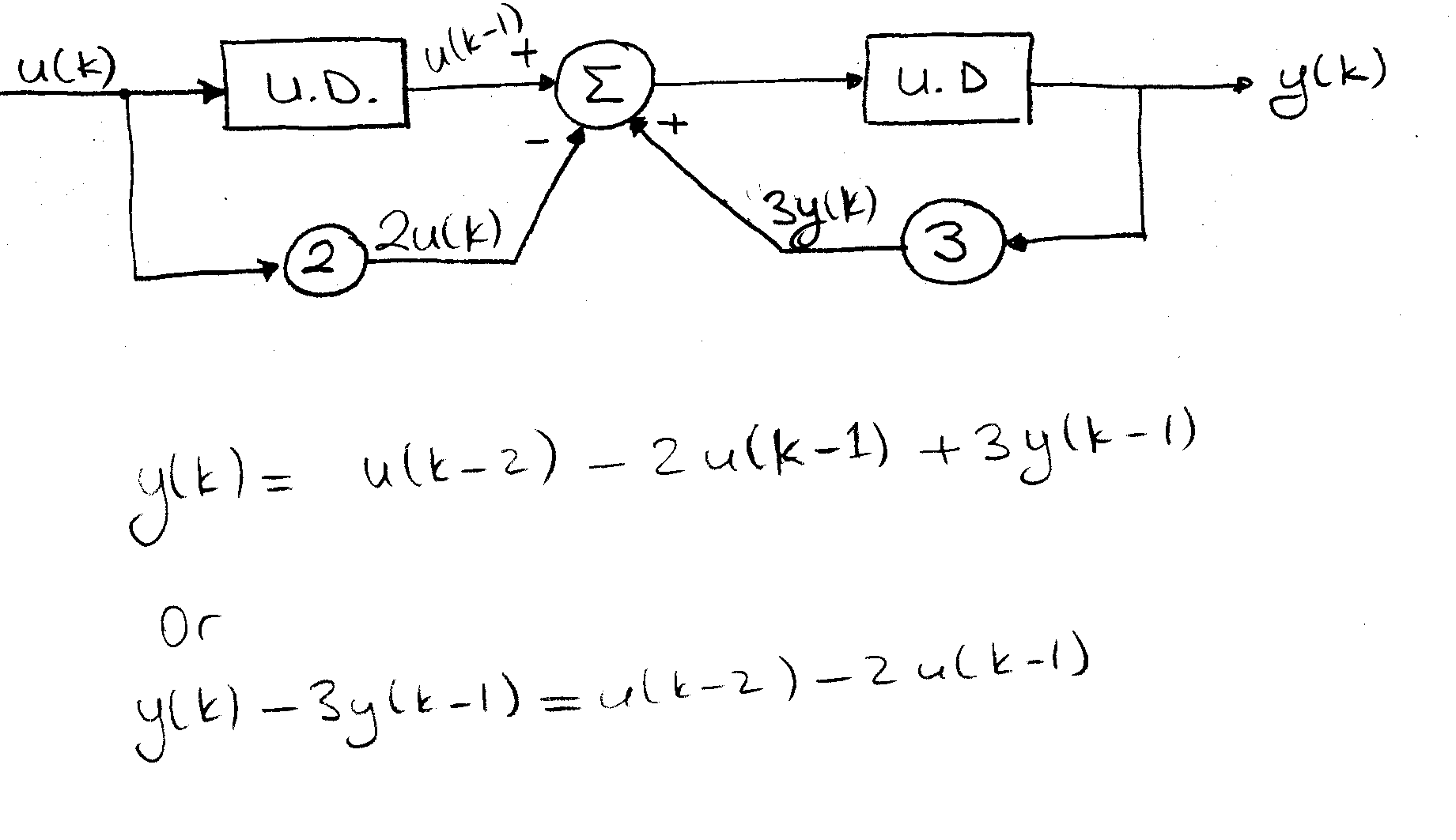
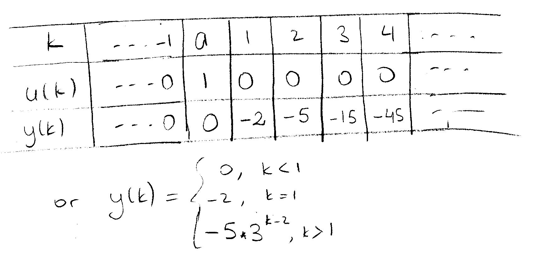
15. Find the impulse response of the system above.
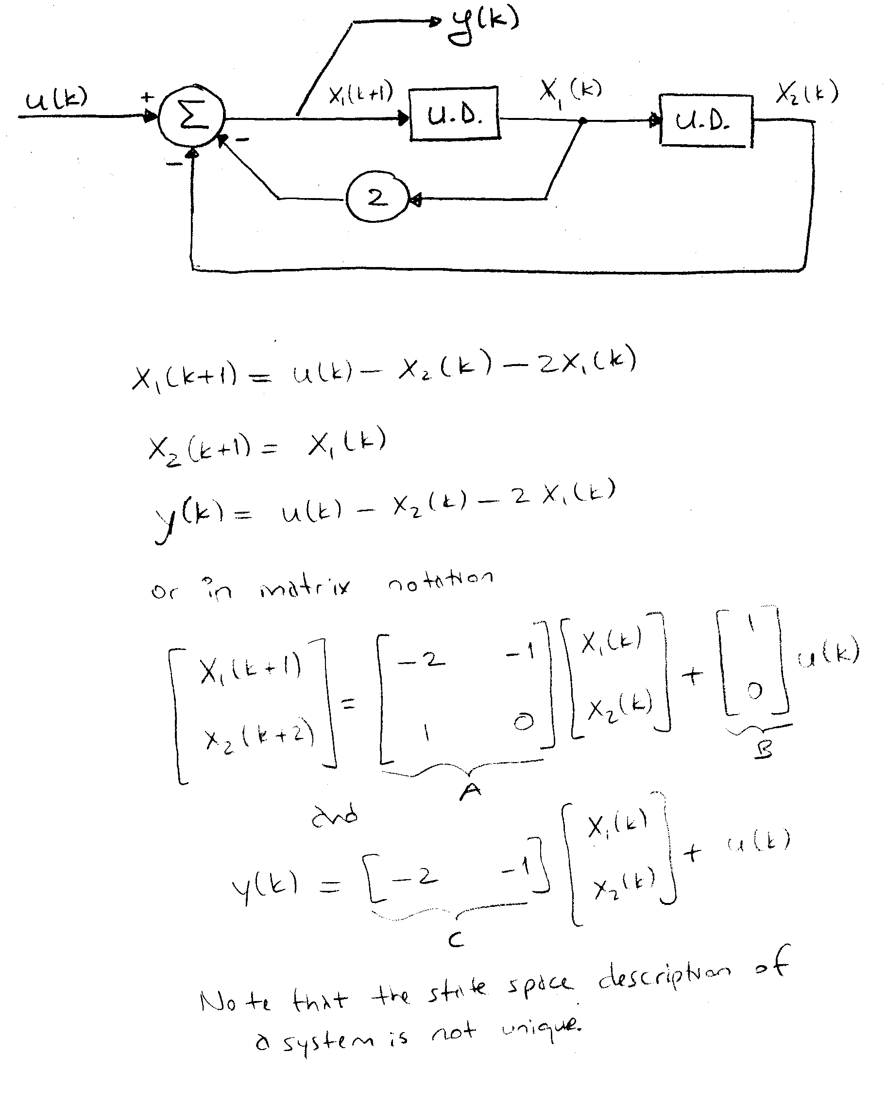
16. Find the state space representation for the system below:
17. The impulse response of a temperature sensor is given by:

If the input sequence to the sensor is given by

Find the output signal.

18. Find the output voltage in the time domain for the following circuit.
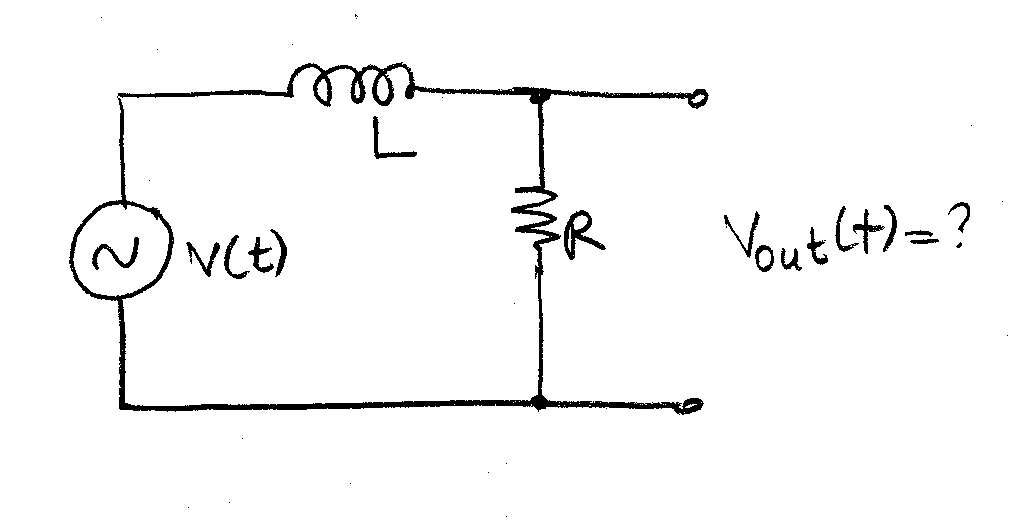
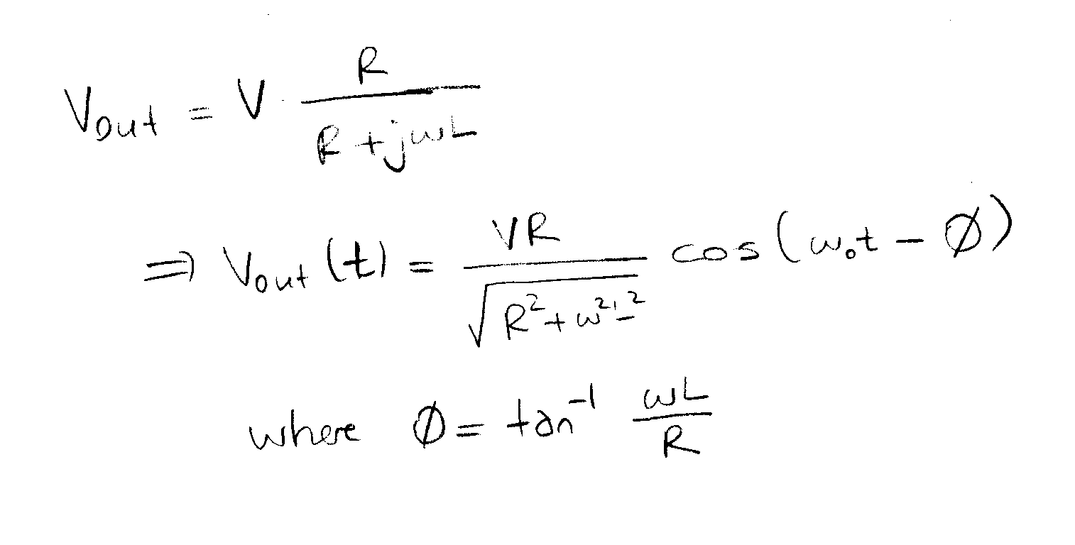
R=1kW , C=1m F, L=1m H
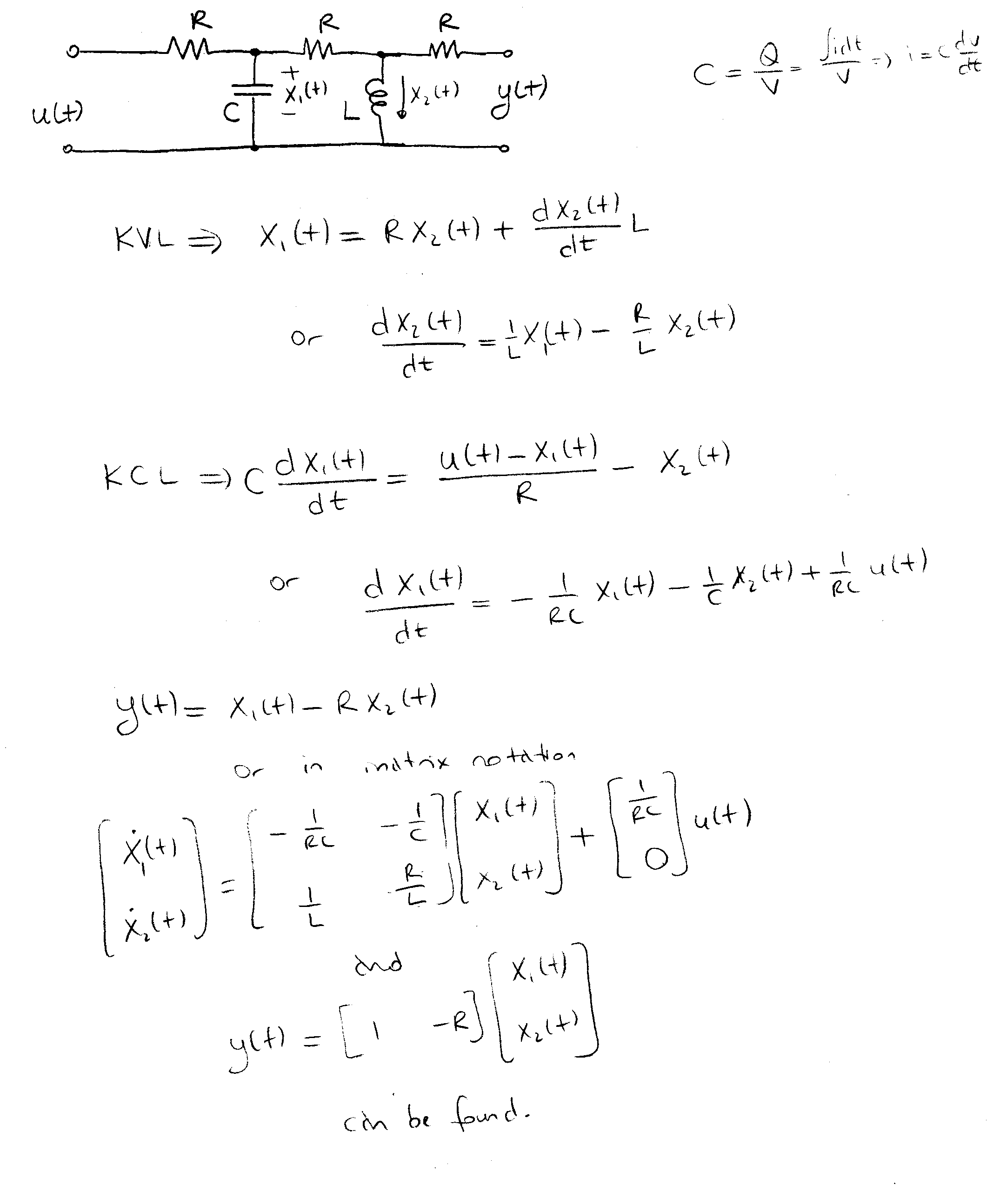
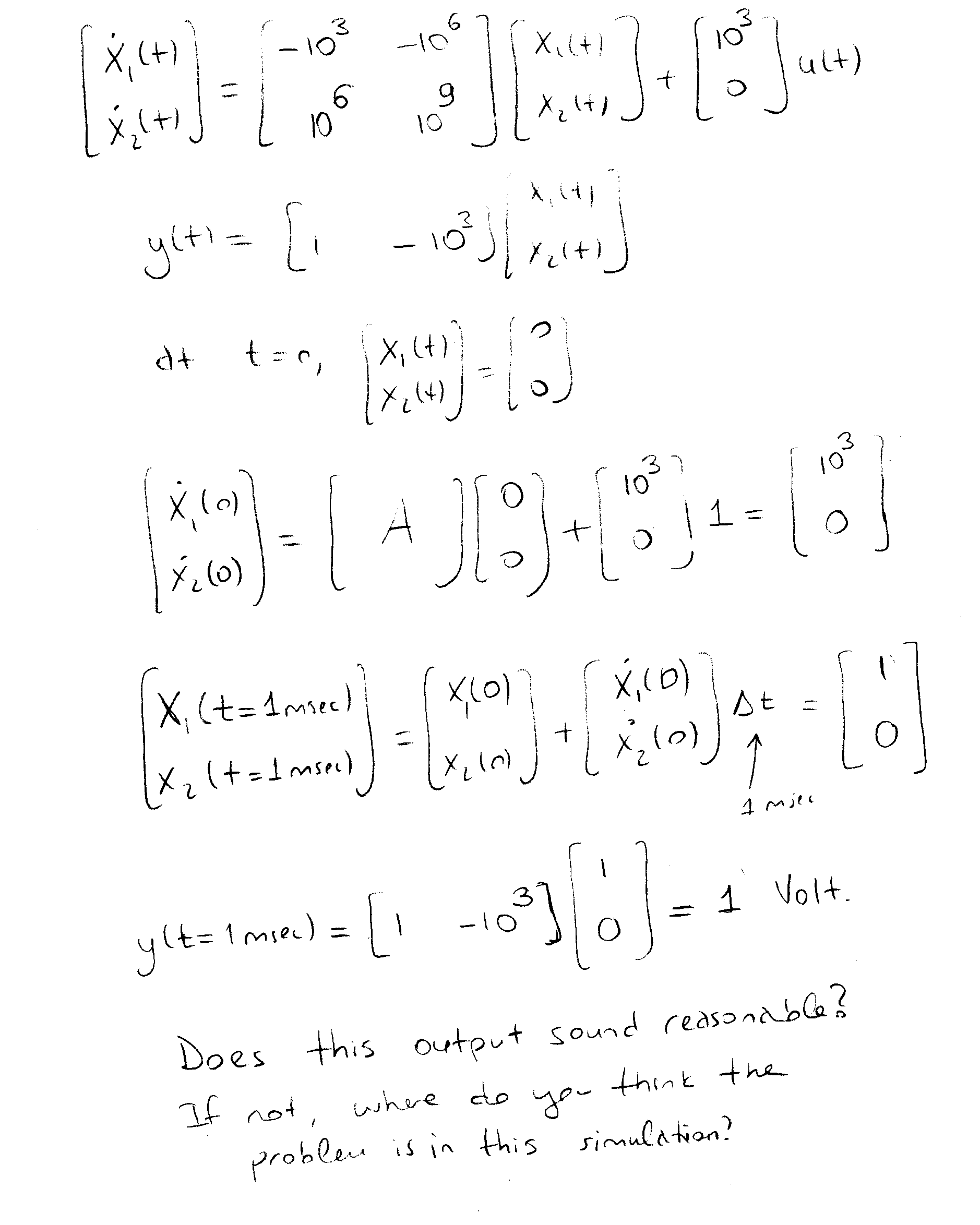
20. Use Eulerís Approximation and iterate the state-space equations above once, for one unit time after t = 0. Assume the applied input is a unit step and D t = 1msec. Find the output y(t=1 msec).
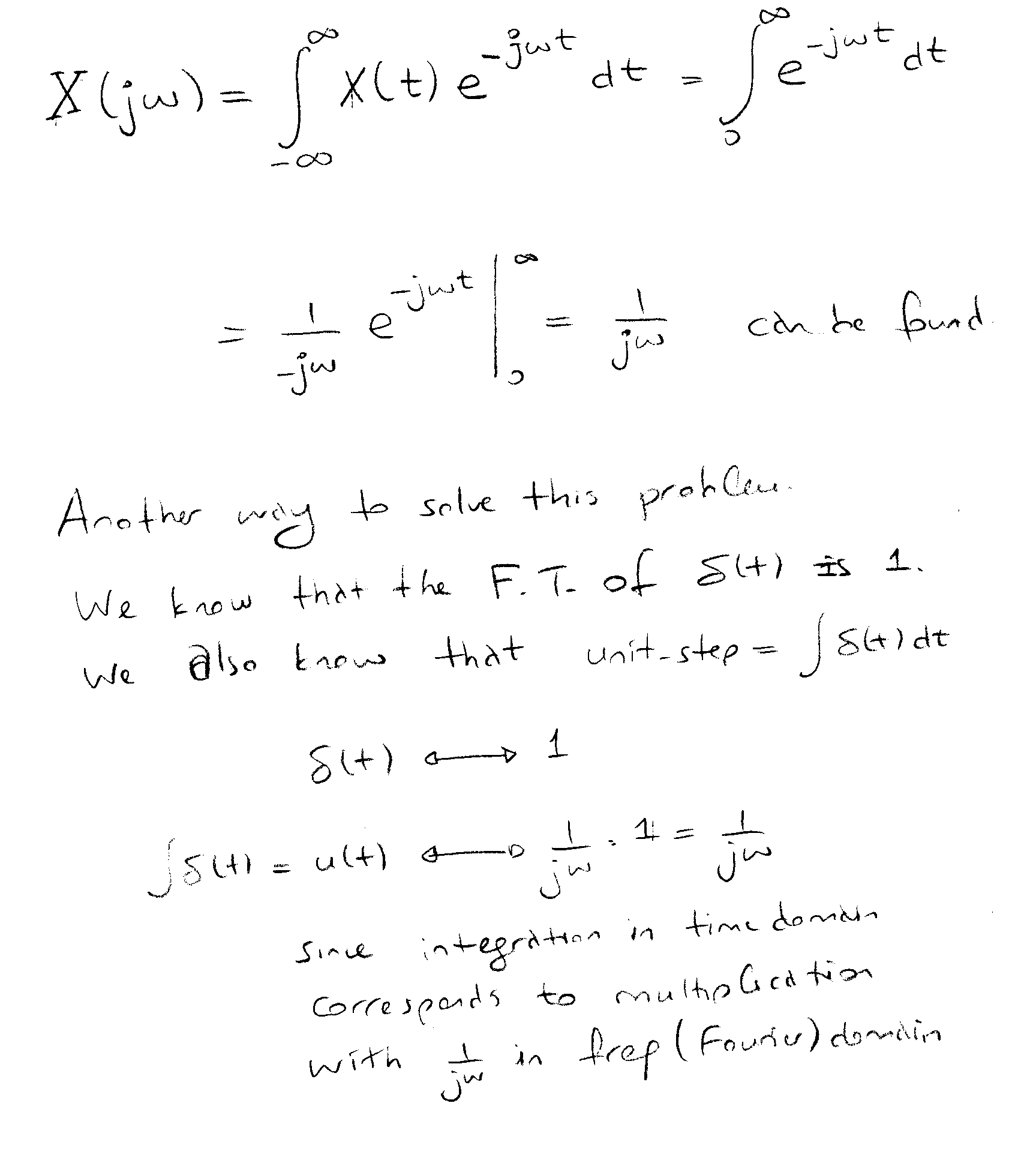
21. Find the Fourier Transform of
![]()
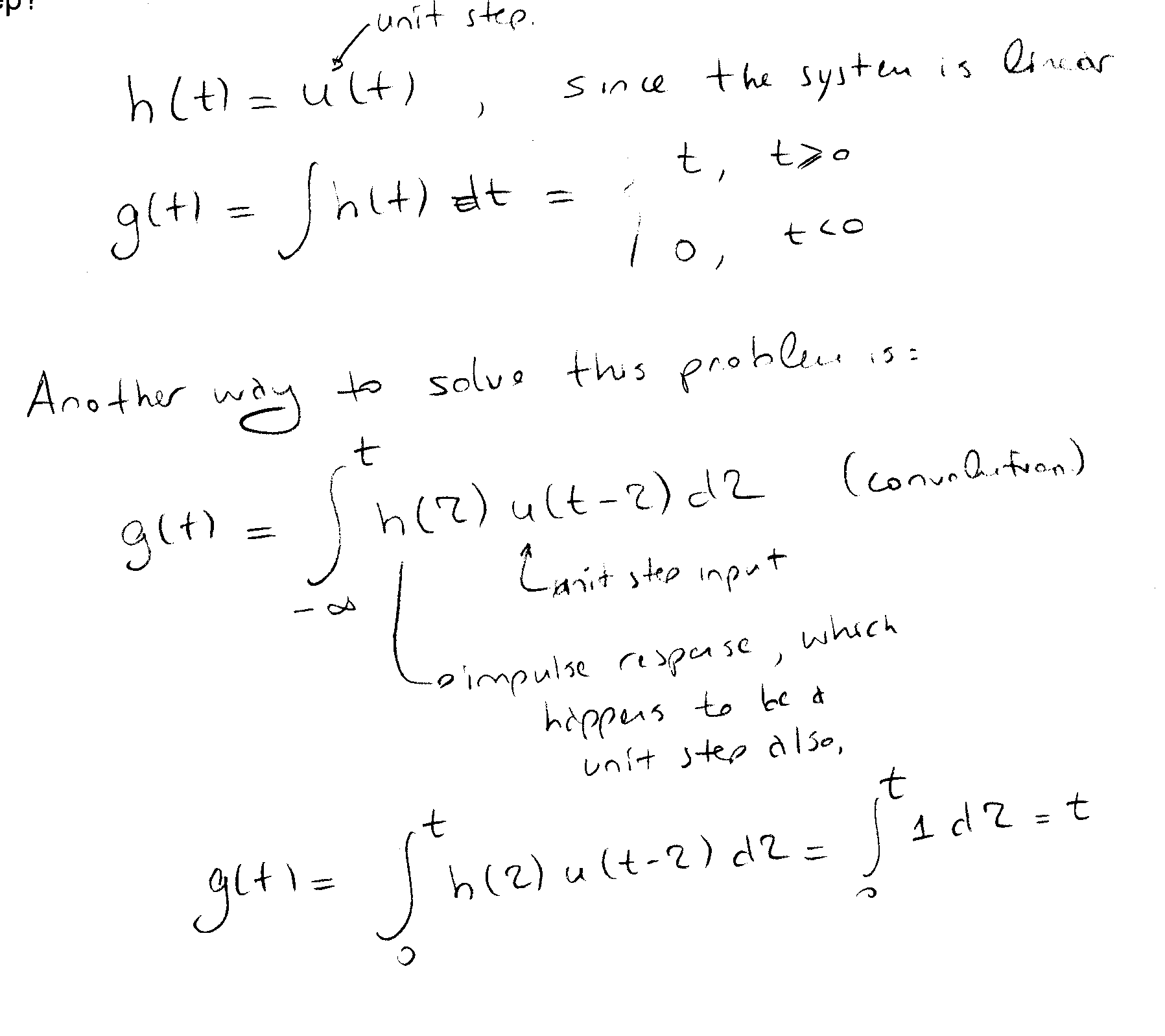
22. Impulse response of a sensor was found to be a unit step. What is its response to a unit step?
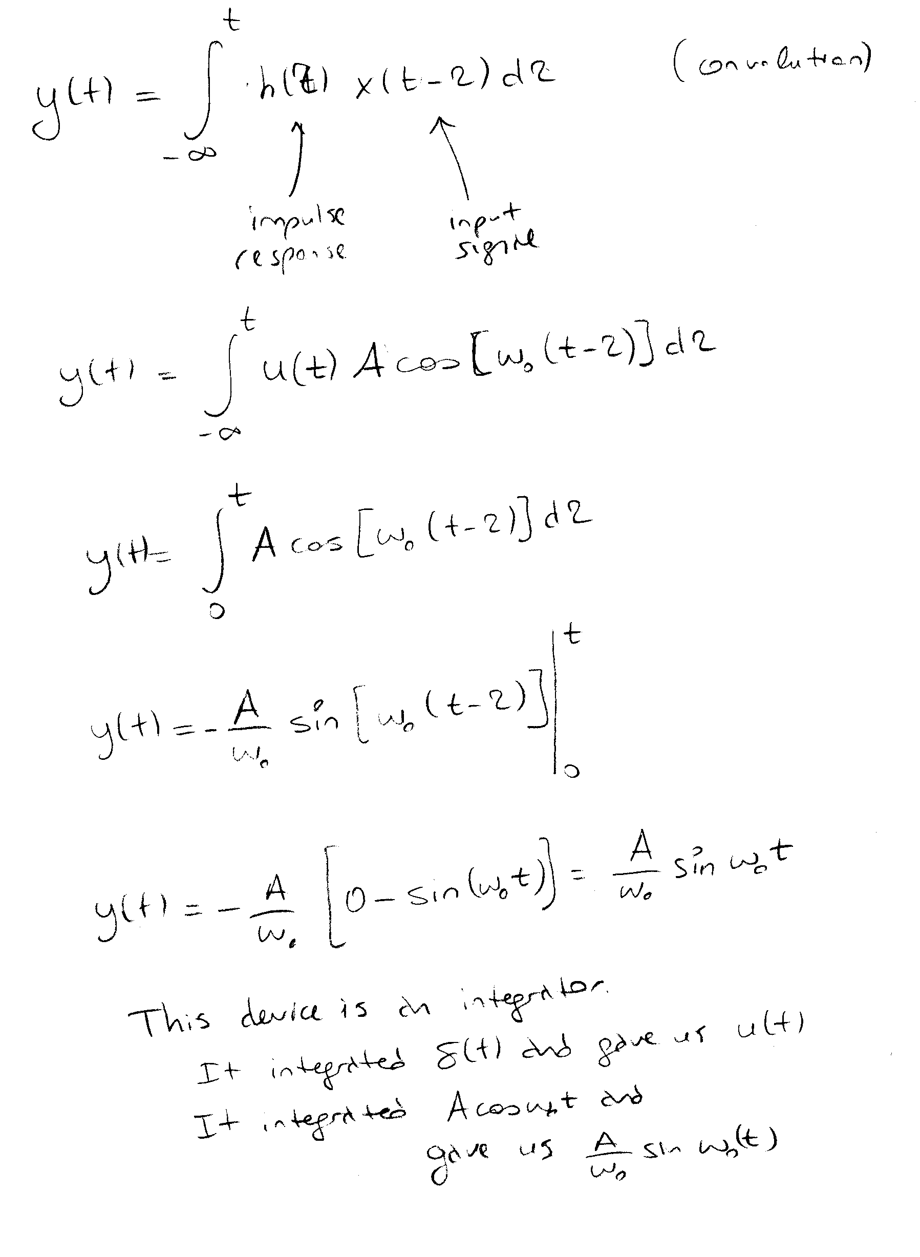
23. What is the response of the sensor above to Acos(w ot)?
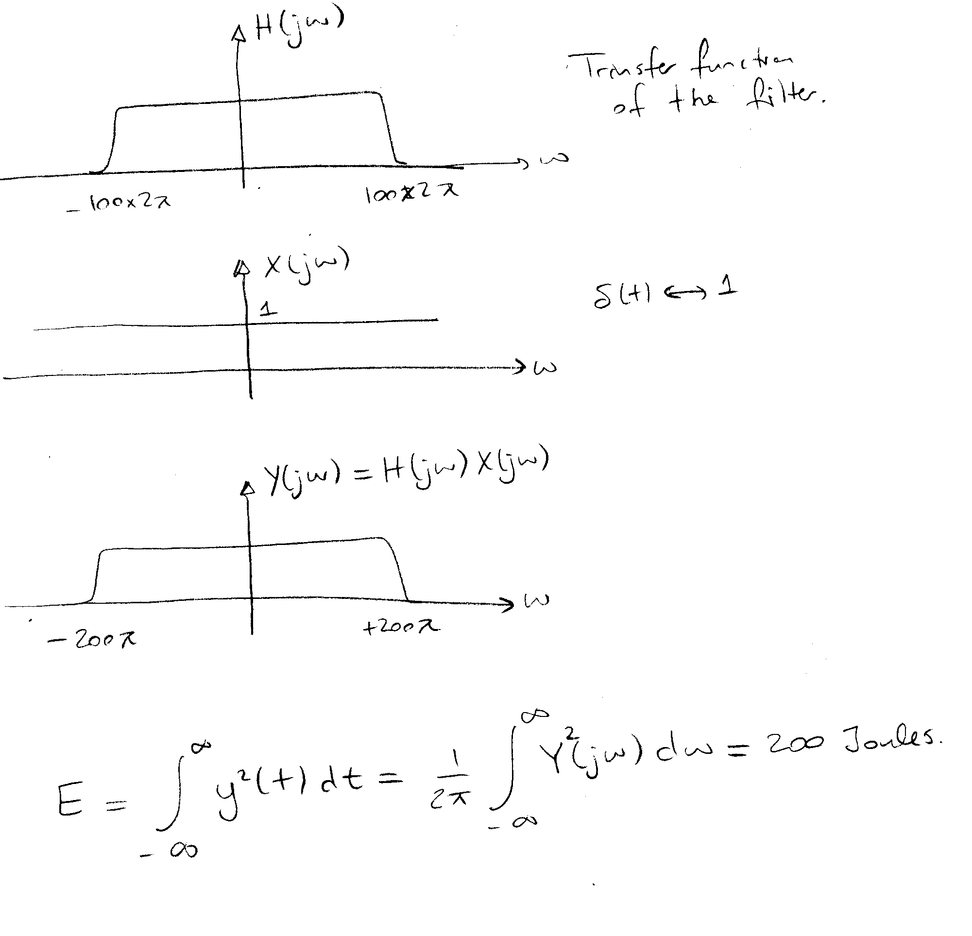
24. You have a low pass filter which allows the passage of signals between DC and 100 Hz with unity gain. If you excite this filter with an impulse function, what is the energy content of the output signal?
25. You are sampling a sine wave:
x(t)=sin(w ot) where w o = 2P f0 and f0 = 250 Hz.
ANSWER: minimum sampling frequency should be 2 x f0 = 500 Hz.
ANSWER: Square wave has harmonics at frequencies fn=nf0, n=odd
As nà ¥ , fnà ¥ , fsampling = ¥
Þ theoretically, it is impossible to sample a square wave with 100% fidelity.