Creating Curves

To create a curve in the xy-plane, you need the following steps:
- Select Edit, followed by
Create. This will put
the curve system in the insert and the cursor is
changed to a cross. Note that the menu item shows
Edit: Create, meaning that
the system is in the insert mode.
- The second step is to specify a curve type. This system supports
four types of curves: Bézier, rational Bézier,
B-spline and NURBS curves. All four types require a set of
control points.
Select Curve, followed by
New Curve Segment, followed
by the curve type you want. For example, if you choose the curve
type to be B-Spline, then
the menu item shows
Curve: B-Spline.
- For Bézier and rational Bézier curves, the degree
of the curve is the number of control points minus 1. For
example, if a Bézier curve is defined by nine control points,
its degree is 8. For B-spline and NURBS curves, one need to
specify the degree of the desired curve. The default degree for
a B-spline and NURBS curve is 3. But, you can change this value
by selecting Degree, followed
by the desired degree. This system supports degree up to 10 for
B-spline and NURBS curves, which is sufficient for more design
purposes. If we choose 4,
the menu item will show
Degree: 4
- Now, you can move the cross pointer into the drawing canvas
and click to put control points there. In the figure below,
we put 13 control points on the drawing canvas. Please note that
the control point IDs start with 0.
As a result, the control points are numbered from 0 to 12.
- Finally, we can display the curve by selecting
Curve, followed by
Show Curve Segment. We have
three choices:
With Uniform Knots,
With Clamped Knots, and
With Closed Knots.
Meanwhile, let us select
With Clamped Knots, since our
study centers around this type of curves. Then, we shall see
the following B-spline curve of degree 4, with clamped knots, on
the drawing canvas.
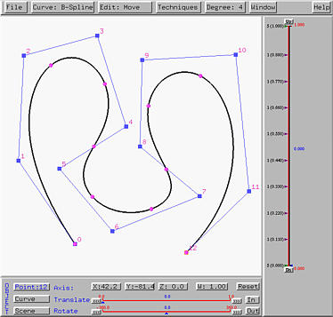
- Recall that the right hand side of the vertical slider is for
curve tracing and the left hand side shows the knots. Each knot
is shown in a form of m (d.ddd),
where m and
d.ddd are the multiplicity and value
of a knot, respectively. After a curve is generated,
all knots are equally spaced.
As mentioned earlier, Bézier and rational Bézier curves
do not require a degree. One can just put control points on the drawing
canvas. As you are clicking, the curve will be generated on-the-fly.
So, creating Bézier and rational Bézier curves are simpler
than creating B-spline and NURBS curves. The following figure shows
a Bézier curve generated from the same set of control points that
were used to created the above B-spline curve. Note that since there are 13
control points, this Bézier curve should have degree 12 as shown
in the Degree: 12.
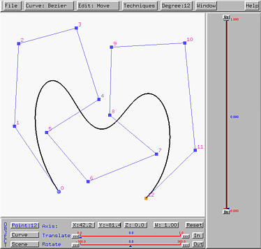
If you compare this Bézier curve with the above B-spline curve, you
will see that the B-spline curve of degree 4 follows the control polygon
more closely than the Bézier curve of degree 12 does. This is a
good reason for using B-spline and NURBS curves, because it allows to use
a lower degree curve to follow the given control polyline closely. However,
Bézier curves are simpler and easier to understand and implement.