
To create a new surface, one should select File followed by New Scene to obtain a fresh draw canvas.
The next step is to select a surface type. There are four supported types, namely Bézier, rational Bézier, B-spline and NURBS. To specify a surface type, select Surface, followed by Surface Type, followed by the type of the surface you want.
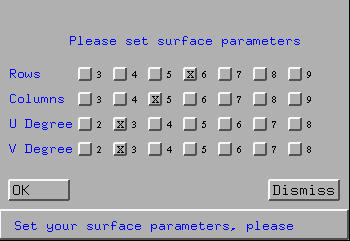
Finally, a surface template of the specified type is needed to start with. To this end, select Edit, followed by Create Surface. Then, a window pops up asking you to set the parameters of the surface to be created (see the figure below). If the type is B-spline or NURBS, this window contains four questions: the number of rows (first row), the number of columns, (second row), the degree in the u-direction (i.e., row direction) and the degree in the v-direction (i.e., column direction). Currently, this system restricts the number of rows and columns to 9 and the u and v degree to 8. Click on the buttons to make your selections. Click on OK to accept your choice; otherwise, click on Dismiss to close this window.
Note that if the selected surface type is Bézier or rational Bézier, the above window will not show the U Degree and V Degree buttons.
If the desired surface is a B-spline or a NURBS surface, this program will automatically generate two sets of uniformly spaced knots, one for the u-direction and the other for the v-direction. The surface will be clamped on both directions.
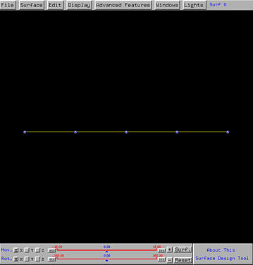
After accepting your choice, this system displays the control net based on the parameters. All control points are coplanar on the xy-plane and as a result only one row can be seen initially. The following figure is obtained with 6 rows, 5 columns, and 3 for both u degree and v degree:
Then, rotations, translations or even zooming are required to bring the control net to a position so that all control points can be seen. You may also want to bring up the Tracing Window, if it is not activated, by selecting Windows followed by Show Tracing Window.
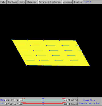
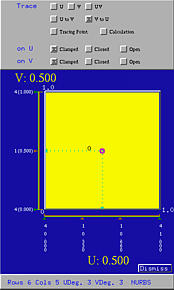
Note that since each row has 5 control points and degree 3, the number of knots for each row is 9. Therefore, in the u-direction, we have 4 knots clamped at 0, another 4 knots clamped at 1, and one internal knot. Similarly, since each column has 6 control points and degree 3, the number of knots is 10. As a result, in the v-direction, we have four knots clamped at 0, another 4 knots clamped at 1, and two internal knots. This can be seen from the Tracing Window.
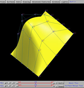
To modify the shape of the surface, one can (1) move control points, (2) change weights, and (3) modify knots. (1) and (2) can be done with the Control Point Window, while (3) can be achieved by dragging the knots in the Tracing Window. With these operations, we may create a surface patch like the following: