A surface of revolution is generated by revolving a given curve about an axis. The given curve is a profile curve while the axis is the axis of revolution..
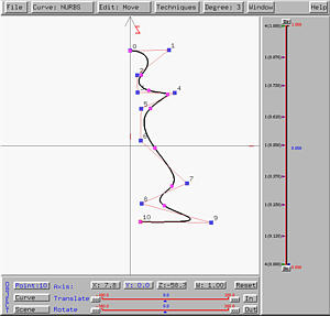
To design a surface of revolution, select Advanced Features followed by Cross Sectional Design. This will bring up the curve system. In the curve system, just design a profile curve based on the condition to be discussed below, and then select Techniques followed by Generate Surface of Revolution. The surface system will display a surface of revolution defined by the given profile curve.
Some special restrictions must be followed in order to design a surface of revolution under the curve system. First, the axis of revolution must be the z-axis. Second, the profile curve must be in the xz-plane. However, when brining up the curve system, only the xy-plane is shown. To overcome this problem, one can design a profile curve on the xy-plane and rotate the curve (not the scene) about the x-axis 90 degree (or -90 degree, depending on your need). In this way, the profile curve will be placed on the xz-plane. Note that to modify control points after this rotation, you must use the sliders.
Many commonly seen and useful surfaces are surfaces of revolution (e.g., spheres, cylinders, cones and tori). Here are a few examples.
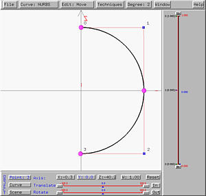
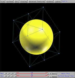
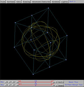
The following shows the generated sphere, shown in rendered patch and wireframe. The top center and bottom center control points correspond to the two endpoints of the semi-circle. Note also the circular wireframe lines which are the loci of points on the semi-circle.
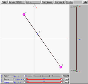
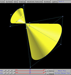
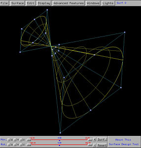
The following shows the generated cone, shown in rendered patch and wireframe. Note that the intersection point of the profile curve and the axis of revolution becomes the vertex (or apex) of the cone. Note also that the profile line segment does not have to intersect the axis of revolution. In this case, the cone's vertex (or apex) will disappear. You can move the line segment away from the z-axis and generate a new surface of revolution to see the effect.
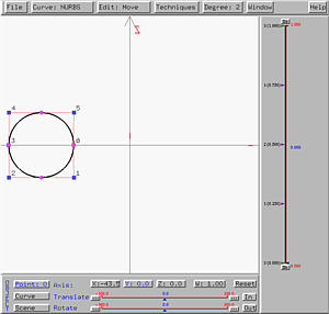
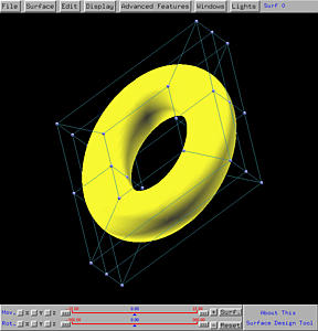
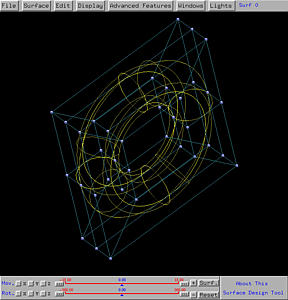
The following shows the generated torus, shown in rendered patch and wireframe. The input circle does not intersect the axis of revolution. If you move the circle so that it is tangent or intersect the axis of revolution, the generate torus will not look like a donuts. For the tangent (resp., intersecting) case, the generate torus is referred to as a spindle torus with one (resp., two) singularities.
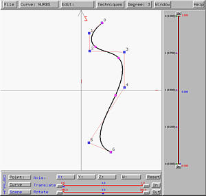
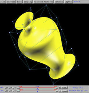
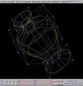
The generate vase-like surface is shown below in both rendered patch and wireframe forms.
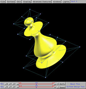
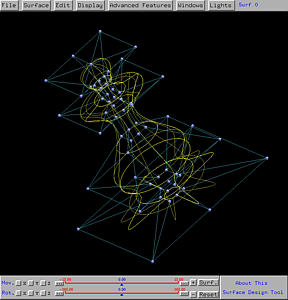
The following shows the chessman-like surface in both rendered patch and wireframe form.