There are three ways of modifying the shape of a curve, namely modifying control points, modifying knots, and modifying the weights of control points. The first works for all four types of curves, the second can be applied to B-spline and NURBS curves, and the third can be used with rational Bézier and NURBS curves. This page concentrates on the first one: modifying the positions of control points.
To modify control points, we can move the existing control points or add new or delete existing ones.
To move a control points, select Edit followed by Move. This puts the system in the move mode and the cursor becomes a north-west pointing arrow. Then, you can click and drag a control point to move it to another place. Note that when you click and drag a control point, it becomes selected and is shown in a different color. Once you release the mouse button, the new coordinates and weight of that control points will be shown in the X, Y, Z and W buttons.
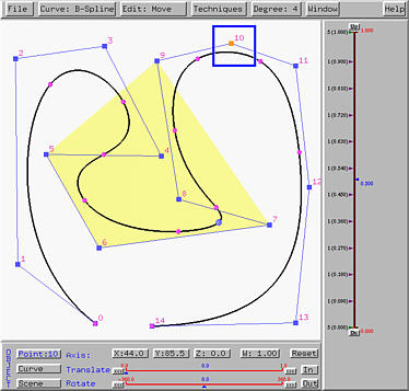
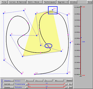
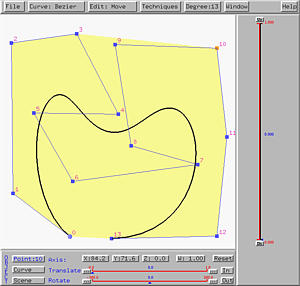
The following figure shows a B-spline curve of degree 4. We first enter the move mode by selecting Edit followed by Move. Then, click on the control point with ID 10. Its coordinates and weight will be shown. In this case, as shown in the following figure, the coordinates of this control point is (44.0, 85.0, 0.0) with weight 1. Note that since this is a B-spline curve, the weight of any control point must be 1. Note also that since this is a curve on the xy-plane, the z-coordinate has value zero.
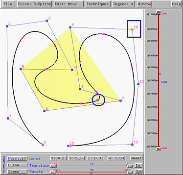
If control point 10 is dragged to a new position as shown in the figure below, its new coordinate values will be updated in the X, Y, Z and W buttons. The new coordinate becomes (67.5,-5.5,0) with weight 1. It is important to notice that when a control point of a B-spline or a NURBS curve moves, only portion of the curve will be affected. This can be seen by comparing the figures above and below. This is the well-known property known as the local modification property and is one of the many advantages of using B-spline and NURBS curves. Modifying the position of a single control point of a Bézier or a rational Bézier curve will change the shape of the curve globally.
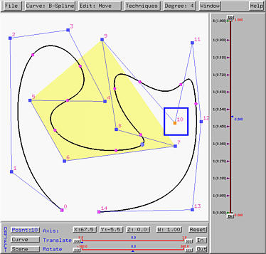
After a few experiments, you will find out that moving a control point will pull the curve in the direction of movement. Note also that moving a control point does not change the specification of the curve (i.e., the number of control points, the number of knots and the degree of the curve). Only the shape of the curve changes.
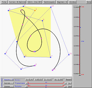
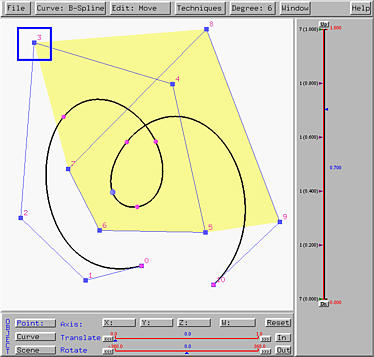
The above is a B-spline curve of degree 4 used earlier in the discussion of moving control points. The point marked with a square is control point 10 and the point marked with an ellipse is the tracing point on the curve corresponding to u = 0.55.
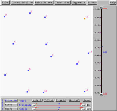
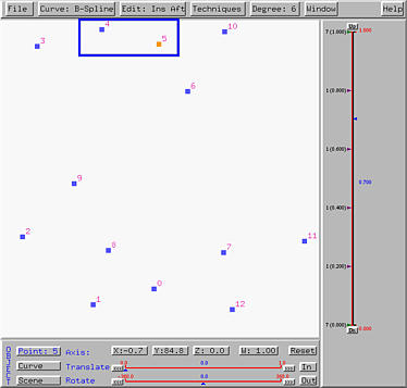
To delete a control point, select Edit, followed by Delete. The cursor changes to a skull, indicating that the system is in the delete mode. Move this delete (or skull) cursor on top of control point 10 and click. Then, the curve, its control polygon and convex hell all disappear. The control point you just clicked on also disappear and all remaining control points are re-numbered. All control points before the deleted one keep the original control point IDs, and all IDs of the remaining control points will be decreased by one. Moreover, the control point with the new ID 10 becomes selected. This is shown below.
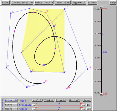
Since deleting a control point has ruined the original curve specification, this system considers you are creating a new one. What you need to do is to display the new curve. Select Curve, followed by Show Curve Segment, followed by With Uniform Knots, With Clamped Knots or With Closed Knots. The new curve will be displayed. The following figure shows the new curve with clamped knots.
Please note that the convex hull for u=0.55 changes. But, the curve itself does not change very much. One can easily notice that the right bulge becomes smaller and the left one of the curve has no change at all. This is due to the local modification property of B-spline and NURBS curve.
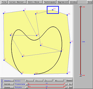
Deleting control points from a Bézier or rational Bézier curve is simpler. One can just delete a control point and due to the impact of deleting a control point on Bézier and rational Bézier curves being global, the system will immediately display the new curve and adjust its degree. The right figure below is the result of deleting control point 10 from the left one.
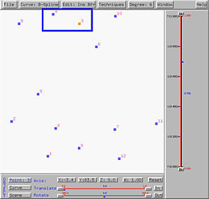
Since control points are ordered, one must specify where the new control points should be placed. This system provides two options Insert After and Insert Before. The following figure shows a B-spline curve of 6 and two more control points will be inserted after control point 3.
To insert new control points after a control point, one need to do two steps: (1) indicating the control point after which new control points will be inserted (i.e., in this case, one should indicate control point 3), and (2) entering the insert mode.
To carry out the first step, if the system is already in move mode, one can click on a control point (i.e., in this case, clicking on control point 3). If the system is not in the move mode, one can either enter the move mode or select Edit followed by Select to enter the select mode. Then, click on the control point you want to select. The difference between the move mode and the select mode is that the former selects a control point and allows you to move it, while the latter only allows you to select a control point.
After a control point is selected, one can select Edit followed by Insert After for inserting new control points after the select one, or Insert Before for inserting new control points before the select one. Let us try insert after first.
Select Edit followed by Insert After. The cursor changes to a cross, meaning that the system is in the insert mode and the menu button displays Ins Aft. Then, each click on the drawing canvas adds a new control points after the selected one. If the selected one is control point k, the new control points will be k+1, k+2 and so on. However, since inserting new control point changes the curve specification, the curve will disappear as we saw in the case of deleting control points. The following shows the result of adding two new control points after control point 3:
To get the curve back, we need to select Curve, followed by Show Curve Segment, followed by With Uniform Knots, With Clamped Knots or With Closed Knots. The new curve will be displayed. The following figure shows the new curve with clamped knots.
Based on this idea, the create mode is actually equivalent to inserting new control points after an imaginary control point, say control point -1.
The process for inserting new control points before a select one is similar. If the selected control point is k, after inserting a new control point before control point k, the new control point becomes k and the original k and all control points after k will be increased by one.
Note that insert after and insert before could have a dramatically different effect even though new control points are inserted at the same locations. The following left figure shows inserting two new control points before control point 3. The positions of the new control points are near to those two we used in insert after. After insertion, the new control points become 3 and 4 and the original control point 3 changes to control point 5. Thus, the curve will have a twist as shown in the right figure.