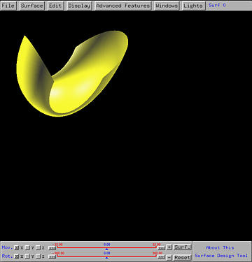

This system supports creating multiple surfaces in the same scene. You can work on one surface and then create a new one so that the original and the new one will be on the same drawing canvas and manipulated separately. Here is an example. Let us use File, followed by Load, followed by Load Default Scene One to load the default scene one on the canvas. Then, move it to the upper left corner, pretending we have done the design job.
While you are working on this surface, you should see Surf 0 near the upper right corner, indicating that this is surface 0. In the Tracing Window, at the center of the domain of (u,v), you will see a 0, indicating that the current surface is surface 0. Moreover, the color of the domain is identical to the color of the surface. Due to lighting effect, the surface color and the domain color may be slightly different.
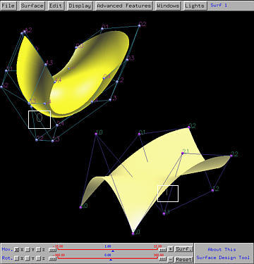
Then, use the technique discussed in Creating Surfaces to create a grid. Once the grid becomes available, Surf 0 is changed to Surf 1, which means the current surface is surface 1, the one just created. Your can use Surface, followed by Set Current Surface, followed by Surface 0, Surface 1 and so on to switch back and forth among those surfaces on the draw canvas.
It is important to know which surface you are working on because some operations are for the whole scene (e.g., using mouse buttons and dragging for translation and rotation) while others can operate on each selected surface (e.g., using the slider for translation and rotation, and displaying control points and control net).
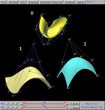
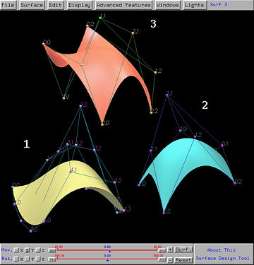
Let us first put a surface ID near by each surface. Choose Display followed by Show Surfaces IDs. Then, each surface is assigned an ID and this ID is used to indicate which surface is the selected one (i.e., the ID of the selected surface is shown near the upper right corner of the drawing window). The white rectangles below indicate the surface IDs.

You can also select a control point and modify its position and weight. Most display options apply to a single surface. Therefore, you can select a surface and display its control points, control point IDs and control net.
If we set surface 0 as the current surface and delete it, the IDs of the remaining surfaces are still the same.
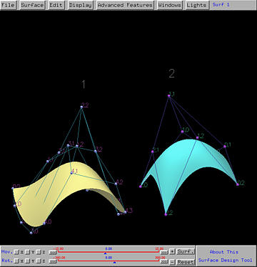
Now if a new surface is created, it will receive a surface ID 3 rather than reuse surface ID 0.
The maximum number of surfaces can be created at the same time is 10.