Swung Surfaces

In the construction of a surface of revolution, the profile curve performs
a complete rotation about the axis of revolution and is never "scaled".
That is, the shape of the profile curve is never changed in the course
of rotation. The swung surface is an extension to the surface of
revolution. We still need a profile curve that rotates about the axis
of revolution; but, the rotation does not have to be 360 degree
and is controlled by a trajectory curve.
Now, the profile curve swings about the axis of revolution, guided by the
trajectory curve. At the same time, the profile curve is also
scaled according to the trajectory curve. Without using mathematics
it is difficult to present complete overview here. But, an example could
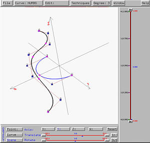
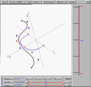
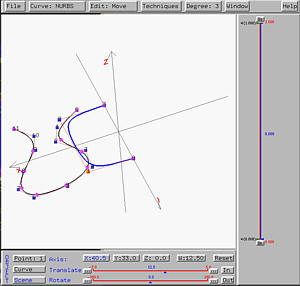
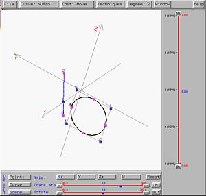
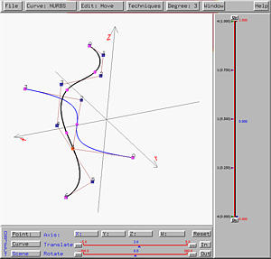
help understand this process. The following figure contains two curves.
The black one (on the xz-plane) is the profile curve, while the
blue curve (on the xy-plane) is the trajectory curve.
Click here to download a copy of this
file swung-2.dat.
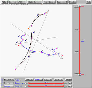
The z-axis is taken to be the axis of revolution. If the profile
curve swings about the z-axis and is scaled by the trajectory
curve in the xy-direction, the generated surface looks like the profile
curve in one direction while looks like the trajectory curve in the other
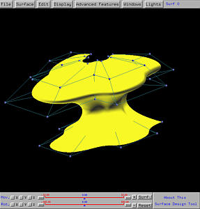
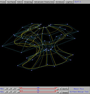
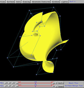
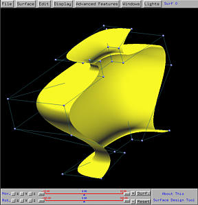
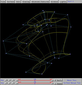
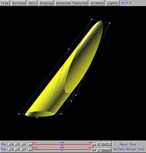
direction. The following
shows the result. It is not difficult to see that the curves that are
approximately horizontal look like the trajectory curve and are scaled
(i.e., if the profile curve has a smaller value at a point, the
"image" of the corresponding trajectory curve becomes smaller).
On the other hand, those vertical curves all have the same shape of the
profile curve. This is the swung surface generated from the given
profile and trajectory curves.
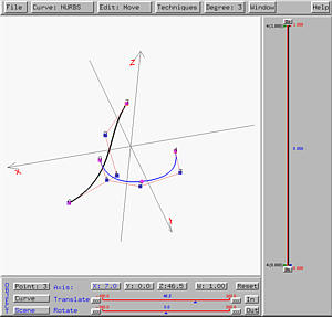
To generate a swung surface, one need to design a profile curve and a
trajectory curve. First, select
Advanced Features followed by
Cross Sectional Design. This will
bring up the curve system. Please always follow the steps below:
- First, design the profile curve in the xz-plane.
You can design this curve in the xy-plane and rotate it
90 degree about the x, bringing it to the xz-plane.
- Then, design the trajectory curve in the xy-plane.
- After adjusting the positions of these two curves,
in the curve system, use
Curve, followed by
Next Curve Segment
to make the profile curve the current curve segment.
- Select Techniques, followed by
Generate Swung Surface.
The swung surface defined by these two curves will be shown
on the drawing canvas of the surface system.
Note that .
One way to avoid this confusion is that design and save each curve
individually and import them back in the right order.
In the following, the profile curve, which must be designed first, is shown
in blank and the trajectory curve is shown in blue.

Example 1: A Half Vase
Let us start with a variation of the vase surface designed in the
discussion of surfaces of revolution.
We take the profile curve of the vase as the profile curve of this swung
surface and put it in the xz-plane. Then, we take the semi-circle,
which is also discussed in the discussion of surface revolution for
generating a sphere, as the trajectory curve. This configuration is shown
in the figure below. Click here
to download a copy of this file
(half-vase.dat) for your practice.
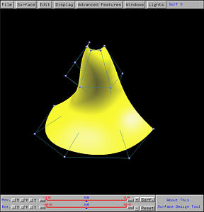
The following is the generated swung surface. As you can see from the
figures, the profile curve provides the "vertical shape" while the
trajectory curve gives the "horizontal shape", which is of course
semi-circular. Please note that due to scaling, this vase is "fatter"
than the one generated by revolution.
Example 2: A Squarish Half Vase
Because the trajectory curve affects the horizontal shape of the generated
swung surface, let us see how to change the circular half vase to a
squarish one. Since the semi-circle is a NURBS curve, we can increase the
weights of the two control points at the corners so that the curve will
be pulled toward the control points. The higher the weights, the closer
the curve to the control points. After modification of weight applied
to the semi-circle, we have the following configuration.
Click here
to download a copy of this file
(sqr-vase.dat) for your practice.
As you see from the following figures, the generated swung vase is more
squarish than the previous one.
Example 3: A Half Bell Surface
Here is another similar example. The profile curve is a stretched letter
S and the trajectory curve is approximately a semi-circular. Thus, swinging
the S shape curve will generate a bell-like surface.
Click here to download a copy of this file
(half-bell.dat) for your practice.
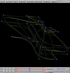
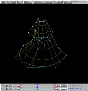
The following shows the resulting swung surface in both rendered patch and
wireframe forms.
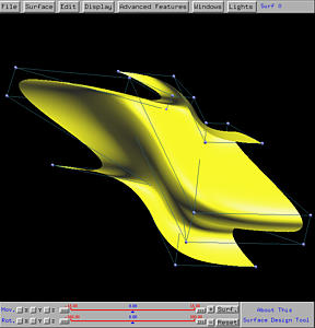
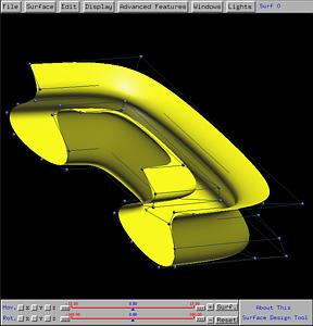
Example 4: Another Swung Surface
The following is an example based on the same idea shown in the previous
three: a profile curve describing the vertical shape and a trajectory
curve describing the horizontal shape.
Click here to download a copy of this file
(swung-3.dat) for your practice.
The following is the resulting swung surface.
Example 5: A Tube
While we emphasize that the profile curve and trajectory curve must be on
the xz- and xy- planes, in many cases this restriction
does not apply. In fact, you can pull both of them off the "standard
positions" to satisfy your need. Here is an example. The profile circle
is a circle not in the xz-plane. In fact, it is designed on the
xz-plane and translated in the x-direction. The trajectory
curve is a line segment (defined as a NURBS curve) in the xy-plane.
Click here to download a copy of this file
(tube.dat) for your practice.
The following is the resulting swung surface. The swinging of the circle
generates a tube (i.e., a cylinder). But, due to the scaling, the two
openings at both ends are not perpendicular to the axis of the cylinder.
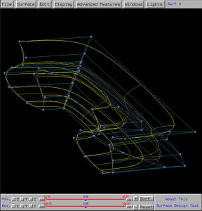
Example 6: A Very Irregular Swung Surface
Normally the trajectory curve in a swung surface design is a simple one,
although the profile curve could be complex. If the trajectory curve
becomes complex, it could be difficult to control the shape of the generated
swung surface. Here is an example, the profile curve is a simple one,
taken from the vase-like surface; however, the trajectory curve takes a S
shape. This would force the profile curve swinging and scaling based on the
S-shaped trajectory curve.
Click here to download a copy of this file
(oop-vase.dat) for your practice.
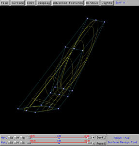
The following is the resulting swung surface. It is clear that in the
horizontal direction the swung surface does have a S shape, while the in the
vertical direction preserves the vase-like shape. However, due to scaling,
the surface looks a little odd.