
The Tracing Window appears when you start the surface system. Or, it can be activated by selecting Windows, followed by Show Tracing Window.
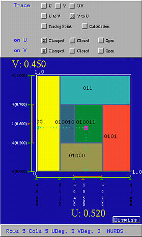
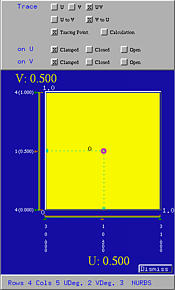
The Tracing Window has three parts. The top part contains buttons for generating and tracing the current surface, the middle part is the domain of the surface (i.e., [0,1]×[0,1]) which is actually used to trace the surface, and the bottom part shows various messages.

The knot vector in the u-direction is shown horizontally, while the knot vector in the v-direction is shown vertically. The knots of the current surface are shown in white color. For the knots in the u-direction, their values are displayed vertically in two rows. The first row gives the multiplicity of knots and the second row displays the knot values. The knots in the v-direction are displayed in the form of m (d.ddd), where m is the knot's multiplicity and d.ddd is the knot's value.
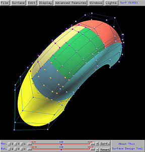
Surface IDs are also shown in the domain in black. If the current surface is subdivided, each subdivision's domain has the same color used in the subpatch. Suppose a surface with ID k is subdivided, yielding two subpatches. The IDs of these two subpatches are k0 and k1. For example, if a subpatch 0100 is subdivided, the two subpatches will have IDs 01000 and 01001. Subpatch k0 inherits the color of the original patch. But, the original surface ID will not be used. In this way, one can easily determine the parent-child relationship among subpatches. The above figures show the matching of colors in the domain and colors used for the subpatches.
To move into a subpatch, click anywhere in its domain. Or, you can also drag the uv-indicator into its domain.
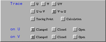
The last two rows of buttons allows you to pick a type of knot sequence for each direction. A surface can be clamped, open, or closed in one or both directions. Since a parametric surface is defined on two variables, u and v, the u-direction (resp., v-direction) is the direction where u (resp., v) can change while v (resp., v) is fixed. You can click on Clamped, Closed, or Open to make the surface clamped, closed or open in a direction. Please refer to Clamped, Open and Closed Surfaces for the meaning of a clamped, closed and open surface.
Selecting Calculation activates the visualization of de Casteljau's or de Boor's algorithms. All intermediate computation steps (i.e., all intermediate control nets) of de Casteljau's or de Boor's algorithm will be displayed. See Tracing the Surface - de Casteljau's and de Boor's Algorithms for the details. Normally, Tracing Point should be selected before selecting Calculation. This will allow both the control nets and tracing point be shown at the same time. However, this is not necessary. If only Calculation is selected, you still can see all control nets except the tracing point.
Selecting V to U instructs the system to do the following:
You can request only to trace an isoparametric curve in the u- or the v- direction. Or, you can request to trace in arbitrary direction without any restriction. Click U (resp., V) allows to trace the surface in the u-direction (resp., the v-direction). More precisely, clicking on U will cause the current value of v fixed and tracing activity only changes the value of u. Clicking on UV allows you to trace the surface in an arbitrary direction (i.e., no restriction in any direction).