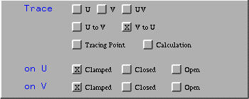

Bézier, rational Bézier, B-spline and NURBS surfaces are parametric surfaces. More precisely, for a point (u,v) in the domain [0,1]×[0,1], it corresponds a unique point S(u,v) on the surface. As (u,v) moves in the domain, S(u,v) traces out the surface. The seven items in the top of the Tracing Window are designed for this purpose.

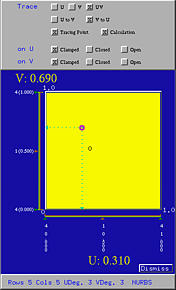
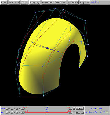
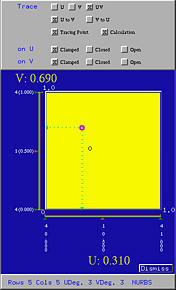
Clicking on Tracing Point activates the simplest tracing activity. You should see a red sphere, the tracing point on the surface. As the uv-indicator moves in the domain, this tracing point moves on the surface, indicating the corresponding point of the current (u,v) on the surface. For example, the following figures show the corresponding tracing point of (0.31,0.69) on the surface.
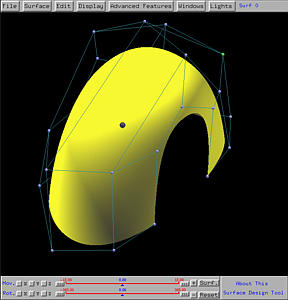
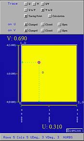
There are three ways of tracing the surface:

Click here for de Casteljau's algorithm for curves, and here for de Casteljau's algorithm for surface. Also, click here for de Boor's algorithm for curves, and here for de Boor's algorithm for surfaces.
To activate de Casteljau's or de Boor's algorithm, click on Calculation. By default, the processing order is V to U; but, clicking on U to V will change the processing order. Note that buttons U, V and UV apply to both de Casteljau's and de Boor's algorithms, since these three buttons provide three different ways of tracing a surface.
If V to U is selected, this means the de Casteljau's or de Boor's net for (u,v) is constructed by applying de Casteljau's or de Boor's algorithm to each row, which defines a curve in the v-direction, and computing a point corresponding to the value of v in (u,v). Thus, for each row we have an intermediate point. These intermediate points define a curve in the u-direction. Applying de Casteljau's or de Boor's algorithm again yields a point on the surface corresponding to (u,v). In the following figure, which is created by clicking on V to U, the red control nets are the control nets in the v-direction, while the blue control net is in the u-direction. Since this is a NURBS surface, de Boor's algorithm is used and as a result, the number of control nets in the v-direction (four, marked in white) is less than the number rows (five).
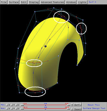
If U to V is selected, the order of this computation is reversed. The intermediate points are in the u-direction while the final tracing point is computed in the v-direction.
As the uv-indicator moves in the domain, the tracing point and the computed control net moves as well.
Click here to download the surface (in file tracing.dat) used on this page for your practice.